You are using an out of date browser. It may not display this or other websites correctly.
You should upgrade or use an alternative browser.
You should upgrade or use an alternative browser.
SD's GXP
- Thread starter SDGTP99
- Start date
Mad Monkey
The Mod Monkey
I think he mean Kayak, and thinks roof rails are like a thule system or something..
I think he mean Kayak, and thinks roof rails are like a thule system or something..
yep, I thought they were so you could put a bar on and off when needed.
MoarkatsINmuhtrailer
New member
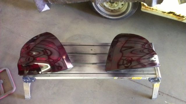
Nahh lol they are nascar inspired
Mad Monkey
The Mod Monkey
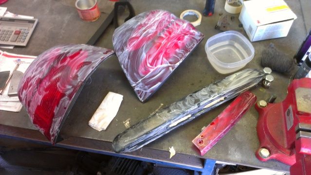
Tails look good. You buy new ones?
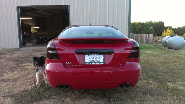
I say that dealer sticker has gotta go.
I say that dealer sticker has gotta go.
Mad Monkey
The Mod Monkey
Oh I just saw them wrapped in plastic and wondered.
TLSheff
New member
So I thought I'd shake up your Member's Ride thread and possibly your day. The throttle body replacement on GXPs, I looked it up and while it doesn't need "programming" per say, it will likely require a Throttle/Idle Learn... which does require a Scan Tool.
Install, appears to be easy, pictures wont work, you won't be able to use the links but the info will tell how to do it.
Removal Procedure
Notice: Handle the electronic throttle control components carefully. Use cleanliness in order to prevent damage. Do not drop the electronic throttle control components. Do not roughly handle the electronic throttle control components. Do not immerse the electronic throttle control components in cleaning solvents of any type. Important:
[TABLE="width: 95%, align: center"]
[TR]
[TD]•[/TD]
[TD]DO NOT for any reason, insert a screwdriver or other small hand tool into the throttle body to hold open the throttle plate as a wedge, as the inside of the throttle body could be damaged.[/TD]
[/TR]
[/TABLE]
[TABLE="width: 95%, align: center"]
[TR]
[TD]•[/TD]
[TD]An 8 digit part identification number is stamped on the throttle body casting. Refer to this number if servicing, or part replacement is required.[/TD]
[/TR]
[/TABLE]
[TABLE="width: 95%, align: center"]
[TR]
[TD]1.[/TD]
[TD]Remove the engine sight shield. Refer to Upper Intake Manifold Sight Shield Replacement .
[/TD]
[/TR]
[/TABLE]
[TABLE="width: 95%, align: center"]
[TR]
[TD]2.[/TD]
[TD]Remove the air cleaner outlet duct. Refer to Air Cleaner Resonator Outlet Duct Replacement .[/TD]
[/TR]
[/TABLE]
[TABLE="width: 95%, align: center"]
[TR]
[TD]3.[/TD]
[TD]Disconnect the throttle actuator control motor electrical connector (3).[/TD]
[/TR]
[/TABLE]
[TABLE="width: 95%, align: center"]
[TR]
[TD]1.[/TD]
[TD]Disconnect the evaporative emission (EVAP) canister purge tube from the throttle body. Refer to Plastic Collar Quick Connect Fitting Service .[/TD]
[/TR]
[/TABLE]
[TABLE="width: 95%, align: center"]
[TR]
[TD]1.[/TD]
[TD]Remove the throttle body bolts (538).[/TD]
[/TR]
[/TABLE]
[TABLE="width: 95%, align: center"]
[TR]
[TD]2.[/TD]
[TD]Remove the throttle body (508).[/TD]
[/TR]
[/TABLE]
[TABLE="width: 95%, align: center"]
[TR]
[TD]3.[/TD]
[TD]Remove and discard the throttle body gasket (509).[/TD]
[/TR]
[/TABLE]
Installation Procedure
Important: DO NOT reuse the throttle body gasket. Install a NEW gasket during assembly.
[TABLE="width: 95%, align: center"]
[TR]
[TD]1.[/TD]
[TD]Install a NEW throttle body gasket (509). Align the locating tab of the gasket with the notch in the manifold.[/TD]
[/TR]
[/TABLE]
[TABLE="width: 95%, align: center"]
[TR]
[TD]2.[/TD]
[TD]Position the throttle body (508) to the intake manifold.[/TD]
[/TR]
[/TABLE]
[TABLE="width: 95%, align: center"]
[TR]
[TD]3.[/TD]
[TD]Install the throttle body bolts (538).[/TD]
[/TR]
[/TABLE]
Tighten
Tighten the bolts to 10 N·m (89 lb in).
[TABLE="width: 95%, align: center"]
[TR]
[TD]1.[/TD]
[TD]Connect the EVAP canister purge tube to the throttle body. Refer to Plastic Collar Quick Connect Fitting Service .[/TD]
[/TR]
[/TABLE]
[TABLE="width: 95%, align: center"]
[TR]
[TD][/TD]
[TD]Important: Verify that the throttle actuator motor harness connector and the connector seal are properly installed and not damaged.[/TD]
[/TR]
[/TABLE]
[TABLE="width: 95%, align: center"]
[TR]
[TD]1.[/TD]
[TD]Connect the throttle actuator control motor electrical connector (3).[/TD]
[/TR]
[/TABLE]
[TABLE="width: 95%, align: center"]
[TR]
[TD]2.[/TD]
[TD]Install the air cleaner outlet duct. Refer to Air Cleaner Resonator Outlet Duct Replacement .[/TD]
[/TR]
[/TABLE]
[TABLE="width: 95%, align: center"]
[TR]
[TD]3.[/TD]
[TD]Install the engine sight shield. Refer to Upper Intake Manifold Sight Shield Replacement .[/TD]
[/TR]
[/TABLE]
[TABLE="width: 95%, align: center"]
[TR]
[TD]4.[/TD]
[TD]Connect a scan tool in order to test for proper throttle opening and throttle closing ranges.[/TD]
[/TR]
[/TABLE]
[TABLE="width: 95%, align: center"]
[TR]
[TD]5.[/TD]
[TD]Operate the accelerator pedal and monitor the throttle angles. The accelerator pedal should operate freely, without binding, between closed throttle, and wide open throttle (WOT).[/TD]
[/TR]
[/TABLE]
[TABLE="width: 95%, align: center"]
[TR]
[TD]6.[/TD]
[TD]Verify that the vehicle meets the following conditions:[/TD]
[/TR]
[/TABLE]
[TABLE="width: 95%, align: center"]
[TR]
[TD][/TD]
[TD]•[/TD]
[TD]The vehicle is not in a reduced engine power mode.[/TD]
[/TR]
[TR]
[TD][/TD]
[TD]•[/TD]
[TD]The ignition is ON.[/TD]
[/TR]
[/TABLE]
[TABLE="width: 95%, align: center"]
[TR]
[TD][/TD]
[TD="colspan: 2"]•[/TD]
[TD]The engine is OFF.[/TD]
[/TR]
[TR]
[TD="colspan: 2"]7.[/TD]
[TD="colspan: 2"]Perform the throttle learn procedure. Refer to Throttle/Idle Learn .[/TD]
[/TR]
[/TABLE]
TLSheff
New member
Hopefully this might help, it reads as if you might be able to do it without using the scan tool to monitor and learn yourself, but I'm not sure, we haven't had to do it at the dealership on a GXP yet.
Throttle/Idle Learn
Description
The engine control module (ECM) learns the airflow through the throttle body to ensure the correct idle. The learned airflow values are stored within the ECM. These values are learned to adjust for production variation and will continuously learn during the life of the vehicle to compensate for reduced airflow due to throttle body coking. Anytime the throttle body airflow rate changes, for example due to cleaning or replacing, the values must be relearned.
An engine that had a heavily coked throttle body that has been cleaned or replaced may take several drive cycles to learn out the coking. To accelerate the process, the scan tool has the ability to reset all learned values back to zero. A new ECM will also have values set to zero.
The idle may be unstable or a DTC may set if the learned values do not match the actual airflow.
Conditions for Running the Throttle Learn Procedure
Reset Procedure
Reset Procedure (Performed after the throttle body is cleaned or replaced)
Throttle/Idle Learn
Description
The engine control module (ECM) learns the airflow through the throttle body to ensure the correct idle. The learned airflow values are stored within the ECM. These values are learned to adjust for production variation and will continuously learn during the life of the vehicle to compensate for reduced airflow due to throttle body coking. Anytime the throttle body airflow rate changes, for example due to cleaning or replacing, the values must be relearned.
An engine that had a heavily coked throttle body that has been cleaned or replaced may take several drive cycles to learn out the coking. To accelerate the process, the scan tool has the ability to reset all learned values back to zero. A new ECM will also have values set to zero.
The idle may be unstable or a DTC may set if the learned values do not match the actual airflow.
Conditions for Running the Throttle Learn Procedure
Reset Procedure
[TABLE="width: 95%, align: center"]
[TR]
[TD="width: 1"]• [/TD]
[TD]DTCs P0068, P0101, P0102, P0103, P0106, P0107, P0108, P0116, P0117, P0118, P0120, P0122, P0123, P0128, P0171, P0172, P0174, P0175, P0201, P0202, P0203, P0204, P0205, P0206, P0220, P0222, P0223, P0300, P0351, P0352, P0353, P0496, P0601, P0604, P0606, P060D, P0641, P0651, P1516, P2101, P2119, P2120, P2122, P2123, P2125, P2127, P2128, P2135, P2138, or P2176 are not set.[/TD]
[/TR]
[/TABLE]
[TABLE="width: 95%, align: center"]
[TR]
[TD="width: 1"]• [/TD]
[TD]Ignition ON, engine OFF.[/TD]
[/TR]
[/TABLE]
[TABLE="width: 95%, align: center"]
[TR]
[TD="width: 1"]• [/TD]
[TD]The vehicle speed sensor (VSS) is 0 km/h (0 mph).[/TD]
[/TR]
[/TABLE]
Learn Procedure[TR]
[TD="width: 1"]• [/TD]
[TD]DTCs P0068, P0101, P0102, P0103, P0106, P0107, P0108, P0116, P0117, P0118, P0120, P0122, P0123, P0128, P0171, P0172, P0174, P0175, P0201, P0202, P0203, P0204, P0205, P0206, P0220, P0222, P0223, P0300, P0351, P0352, P0353, P0496, P0601, P0604, P0606, P060D, P0641, P0651, P1516, P2101, P2119, P2120, P2122, P2123, P2125, P2127, P2128, P2135, P2138, or P2176 are not set.[/TD]
[/TR]
[/TABLE]
[TABLE="width: 95%, align: center"]
[TR]
[TD="width: 1"]• [/TD]
[TD]Ignition ON, engine OFF.[/TD]
[/TR]
[/TABLE]
[TABLE="width: 95%, align: center"]
[TR]
[TD="width: 1"]• [/TD]
[TD]The vehicle speed sensor (VSS) is 0 km/h (0 mph).[/TD]
[/TR]
[/TABLE]
[TABLE="width: 95%, align: center"]
[TR]
[TD="width: 1"]• [/TD]
[TD]DTCs P0068, P0101, P0102, P0103, P0106, P0107, P0108, P0116, P0117, P0118, P0120, P0122, P0123, P0128, P0171, P0172, P0174, P0175, P0201, P0202, P0203, P0204, P0205, P0206, P0220, P0222, P0223, P0300, P0351, P0352, P0353, P0496, P0601, P0604, P0606, P060D, P0641, P0651, P1516, P2101, P2119, P2120, P2122, P2123, P2125, P2127, P2128, P2135, P2138, or P2176 are not set.[/TD]
[/TR]
[/TABLE]
[TABLE="width: 95%, align: center"]
[TR]
[TD="width: 1"]• [/TD]
[TD]The engine speed is between 450–4,000 RPM.[/TD]
[/TR]
[/TABLE]
[TABLE="width: 95%, align: center"]
[TR]
[TD="width: 1"]• [/TD]
[TD]The manifold absolute pressure (MAP) is greater than 5 kPa.[/TD]
[/TR]
[/TABLE]
[TABLE="width: 95%, align: center"]
[TR]
[TD="width: 1"]• [/TD]
[TD]The mass air flow (MAF) is greater than 2 g/s.[/TD]
[/TR]
[/TABLE]
[TABLE="width: 95%, align: center"]
[TR]
[TD="width: 1"]• [/TD]
[TD]The ignition voltage is greater than 10 volts.[/TD]
[/TR]
[/TABLE]
Throttle Learn[TR]
[TD="width: 1"]• [/TD]
[TD]DTCs P0068, P0101, P0102, P0103, P0106, P0107, P0108, P0116, P0117, P0118, P0120, P0122, P0123, P0128, P0171, P0172, P0174, P0175, P0201, P0202, P0203, P0204, P0205, P0206, P0220, P0222, P0223, P0300, P0351, P0352, P0353, P0496, P0601, P0604, P0606, P060D, P0641, P0651, P1516, P2101, P2119, P2120, P2122, P2123, P2125, P2127, P2128, P2135, P2138, or P2176 are not set.[/TD]
[/TR]
[/TABLE]
[TABLE="width: 95%, align: center"]
[TR]
[TD="width: 1"]• [/TD]
[TD]The engine speed is between 450–4,000 RPM.[/TD]
[/TR]
[/TABLE]
[TABLE="width: 95%, align: center"]
[TR]
[TD="width: 1"]• [/TD]
[TD]The manifold absolute pressure (MAP) is greater than 5 kPa.[/TD]
[/TR]
[/TABLE]
[TABLE="width: 95%, align: center"]
[TR]
[TD="width: 1"]• [/TD]
[TD]The mass air flow (MAF) is greater than 2 g/s.[/TD]
[/TR]
[/TABLE]
[TABLE="width: 95%, align: center"]
[TR]
[TD="width: 1"]• [/TD]
[TD]The ignition voltage is greater than 10 volts.[/TD]
[/TR]
[/TABLE]
Reset Procedure (Performed after the throttle body is cleaned or replaced)
[TABLE="width: 95%, align: center"]
[TR]
[TD="width: 15"]1. [/TD]
[TD]Ignition ON, engine OFF, perform the Idle Learn Reset in Module Setup with a scan tool.[/TD]
[/TR]
[/TABLE]
[TABLE="width: 95%, align: center"]
[TR]
[TD="width: 15"]2. [/TD]
[TD]Start the engine and monitor the TB Idle Airflow Compensation parameter. The TB Idle Airflow Compensation value should equal 0 percent and the engine should be idling at a normal idle speed.[/TD]
[/TR]
[/TABLE]
[TABLE="width: 95%, align: center"]
[TR]
[TD="width: 15"]3. [/TD]
[TD]Clear the DTCs and return to the diagnostic that referred you here.[/TD]
[/TR]
[/TABLE]
Learn Procedure (Performed after the ECM is flashed or replaced)[TR]
[TD="width: 15"]1. [/TD]
[TD]Ignition ON, engine OFF, perform the Idle Learn Reset in Module Setup with a scan tool.[/TD]
[/TR]
[/TABLE]
[TABLE="width: 95%, align: center"]
[TR]
[TD="width: 15"]2. [/TD]
[TD]Start the engine and monitor the TB Idle Airflow Compensation parameter. The TB Idle Airflow Compensation value should equal 0 percent and the engine should be idling at a normal idle speed.[/TD]
[/TR]
[/TABLE]
[TABLE="width: 95%, align: center"]
[TR]
[TD="width: 15"]3. [/TD]
[TD]Clear the DTCs and return to the diagnostic that referred you here.[/TD]
[/TR]
[/TABLE]
[TABLE="width: 95%, align: center"]
[TR]
[TD="width: 15"][/TD]
[TD]
Note: Do NOT perform this procedure if DTCs are set. Refer to Diagnostic Trouble Code (DTC) List - Vehicle .[/TD]
[/TR]
[/TABLE]
[TABLE="width: 95%, align: center"]
[TR]
[TD="width: 15"]1. [/TD]
[TD]Start and idle the engine for 3 minutes.[/TD]
[/TR]
[/TABLE]
[TABLE="width: 95%, align: center"]
[TR]
[TD="width: 15"]2. [/TD]
[TD]With a scan tool, monitor the Desired Idle Speed and the actual Engine Speed.[/TD]
[/TR]
[/TABLE]
[TABLE="width: 95%, align: center"]
[TR]
[TD="width: 15"]3. [/TD]
[TD]The ECM will start to learn the new idle cells and Desired Idle Speed should start to decrease.[/TD]
[/TR]
[/TABLE]
[TABLE="width: 95%, align: center"]
[TR]
[TD="width: 15"]4. [/TD]
[TD]Ignition OFF for 60 seconds.[/TD]
[/TR]
[/TABLE]
[TABLE="width: 95%, align: center"]
[TR]
[TD="width: 15"]5. [/TD]
[TD]Start and idle the engine for 3 minutes.[/TD]
[/TR]
[/TABLE]
[TABLE="width: 95%, align: center"]
[TR]
[TD="width: 15"]6. [/TD]
[TD]After the 3 minute run time the engine should be idling normal.[/TD]
[/TR]
[/TABLE]
[TABLE="width: 95%, align: center"]
[TR]
[TD="width: 10"][/TD]
[TD]
Note: During the drive cycle the check engine light may come on with idle speed DTCs. If idle speed codes are set, clear codes so the ECM can continue to learn.[/TD]
[/TR]
[/TABLE]
[TABLE="width: 95%, align: center"]
[TR]
[TD="width: 18"]⇒[/TD]
[TD]If the engine idle speed has not been learned the vehicle will need to be driven at speeds above 70 km/h (44 mph) with several decelerations and extended idles.[/TD]
[/TR]
[/TABLE]
[TABLE="width: 95%, align: center"]
[TR]
[TD="width: 15"]7. [/TD]
[TD]After the drive cycle, the engine should be idling normally.[/TD]
[/TR]
[/TABLE]
[TABLE="width: 95%, align: center"]
[TR]
[TD="width: 18"]⇒[/TD]
[TD]If the engine idle speed has not been learned, turn OFF the ignition for 60 seconds and repeat step 6.[/TD]
[/TR]
[/TABLE]
[TABLE="width: 95%, align: center"]
[TR]
[TD="width: 15"]8. [/TD]
[TD]Once the engine speed has returned to normal, clear DTCs and return to the diagnostic that referred you here.[/TD]
[/TR]
[/TABLE]
[TR]
[TD="width: 15"][/TD]
[TD]
Note: Do NOT perform this procedure if DTCs are set. Refer to Diagnostic Trouble Code (DTC) List - Vehicle .[/TD]
[/TR]
[/TABLE]
[TABLE="width: 95%, align: center"]
[TR]
[TD="width: 15"]1. [/TD]
[TD]Start and idle the engine for 3 minutes.[/TD]
[/TR]
[/TABLE]
[TABLE="width: 95%, align: center"]
[TR]
[TD="width: 15"]2. [/TD]
[TD]With a scan tool, monitor the Desired Idle Speed and the actual Engine Speed.[/TD]
[/TR]
[/TABLE]
[TABLE="width: 95%, align: center"]
[TR]
[TD="width: 15"]3. [/TD]
[TD]The ECM will start to learn the new idle cells and Desired Idle Speed should start to decrease.[/TD]
[/TR]
[/TABLE]
[TABLE="width: 95%, align: center"]
[TR]
[TD="width: 15"]4. [/TD]
[TD]Ignition OFF for 60 seconds.[/TD]
[/TR]
[/TABLE]
[TABLE="width: 95%, align: center"]
[TR]
[TD="width: 15"]5. [/TD]
[TD]Start and idle the engine for 3 minutes.[/TD]
[/TR]
[/TABLE]
[TABLE="width: 95%, align: center"]
[TR]
[TD="width: 15"]6. [/TD]
[TD]After the 3 minute run time the engine should be idling normal.[/TD]
[/TR]
[/TABLE]
[TABLE="width: 95%, align: center"]
[TR]
[TD="width: 10"][/TD]
[TD]
Note: During the drive cycle the check engine light may come on with idle speed DTCs. If idle speed codes are set, clear codes so the ECM can continue to learn.[/TD]
[/TR]
[/TABLE]
[TABLE="width: 95%, align: center"]
[TR]
[TD="width: 18"]⇒[/TD]
[TD]If the engine idle speed has not been learned the vehicle will need to be driven at speeds above 70 km/h (44 mph) with several decelerations and extended idles.[/TD]
[/TR]
[/TABLE]
[TABLE="width: 95%, align: center"]
[TR]
[TD="width: 15"]7. [/TD]
[TD]After the drive cycle, the engine should be idling normally.[/TD]
[/TR]
[/TABLE]
[TABLE="width: 95%, align: center"]
[TR]
[TD="width: 18"]⇒[/TD]
[TD]If the engine idle speed has not been learned, turn OFF the ignition for 60 seconds and repeat step 6.[/TD]
[/TR]
[/TABLE]
[TABLE="width: 95%, align: center"]
[TR]
[TD="width: 15"]8. [/TD]
[TD]Once the engine speed has returned to normal, clear DTCs and return to the diagnostic that referred you here.[/TD]
[/TR]
[/TABLE]
DirtDog
New member
You notice any difference in handling?
When u installed the strut braces in front and rear did u notice any difference at all? I've been debating getting then
Sent from my pager using Morse code. ... .. ... ....