machinegunsquid
New member
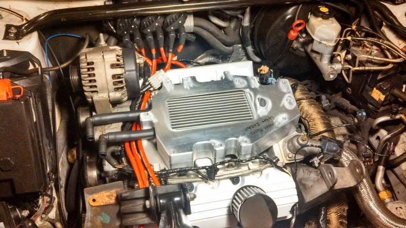
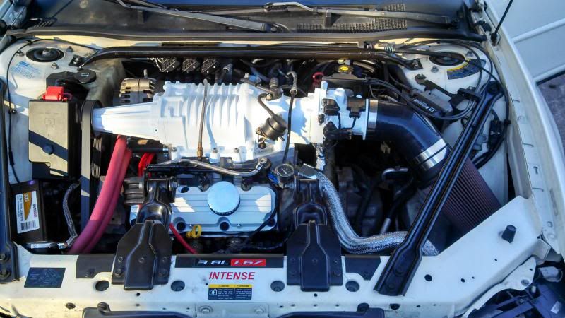
Time to install your newly acquired intercooler!
First and foremost use common sense and don't skimp out or use short cuts.
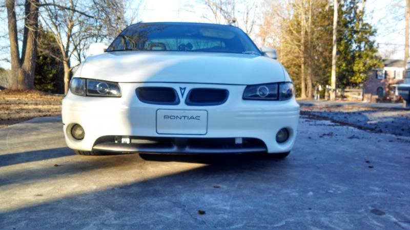
Secondly, any modifications that took place I did as I deemed fit, you may decide to route your hoses a different way, not cut a piece that I did, etc. This write-up is to give a good insight on your own install. This was done on a 2002 GTP so your car may be different (GT's that are topswapped, 04+ etc)
So lets hop to it shall we?
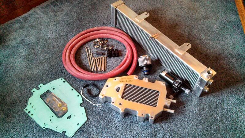
Here is your Intercooler kit (the cores are known to be different, fret not they should all still install the same way)
First things first, disconnect your battery.
We're going to need to get the LIM out, so check out any write-ups or this video for more detailed steps.
You will need to remove your intake from the throttlebody
You will need to remove all the electrical connections on the top end of the motor to get the wiring harness out of the way.
You will need to remove both the supercharger belt, and the accessory belt.
*both are 15mm
You will need to remove the vacuum lines from the fuel rail, LIM, and Map sensor.
You will need to remove the fuel rail (Stock fuel rail cannot be used on a fullsize intercooler install unless it is modified) and have some sort of intercooler compatible fuel rail to install in place of the stock rails
Be sure to bleed any pressure off before disconnecting the fuel rail, and have rags handy to catch the fuel that will spill out.
*Some people will simply unbolt the fuel rail from the LIM and leave the fuel lines connected and pull it out of the way. I do not do this as there is the chance to damage an injector, or possibly crack/break the fuel lines*
*Fuel rail removed, most electrical connections disconnected, belts off*
Once you have everything clear of the supercharger, remove all of the bolts holding the supercharger to the LIM. None of the bolts will be reused.
Make sure you have a good surface to set the supercharger on (a large piece of cardboard works great)
Go ahead and lift the supercharger off of the LIM. There should be little resistance, if any is felt, ensure you have all the bolts removed.
*disregard the changing colors of stuff, pics were taken at different times*
Now that the supercharger is clear, you need to pull the LIM off (either to replace it with a ported LIM from a vendor, or so that we can port our own LIM) You will need to drain some coolant so that you dont get any into the lifter valley. I have personally found it the easiest to loosen the lower radiator hose from the water pump, and let it pour out there, this way you are not emptying the radiator and loosing more coolant.
Once you have the coolant below the level of the LIM, we can go ahead and pull it. Either remove the hose from the T-stat housing, or unbolt the T-stat housing from the LIM and move the hose/housing out of the way.
Remove the alternator
Remove the alternator mount/accessory belt tensioner
Remove the EGR from the LIM
Remove all the bolts for the LIM

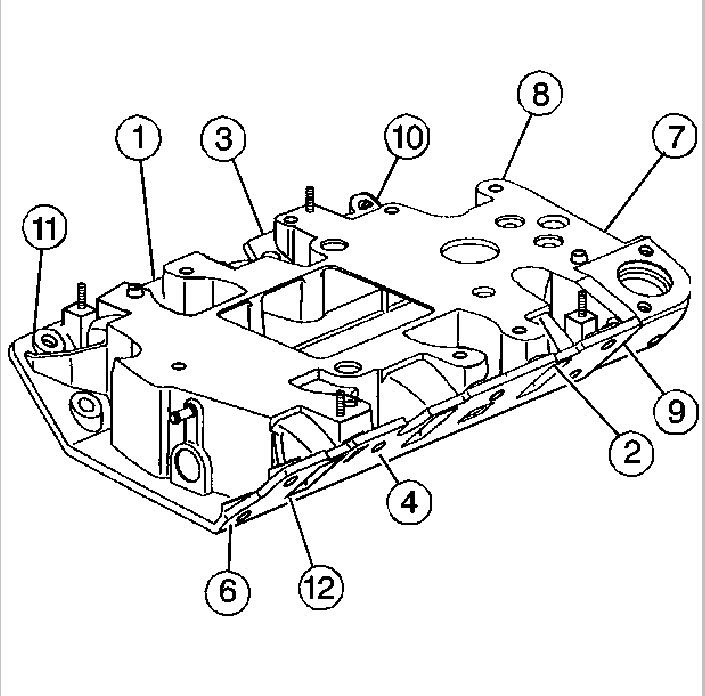
*not my image, using this as reference for the bolts that need to be removed*
Remove the LIM keeping it as level as possible to reduce the amount of coolant spilled into the lifter valley.
*You may need to tap the LIM up with a soft faced hammer, but usually a quick upward lift will suffice*
Use something to cover the lifter valley so that you get no foreign materials in there. Paper-towels or a large rag work well.
Time to modify the LIM so that we get the most surface area for the intercooler core, and get better coolant flow between the back and front heads.
Remove the 2 8mm bolts from the coolant end cap.
Only port the insides of the coolant passage, not the outer edges.
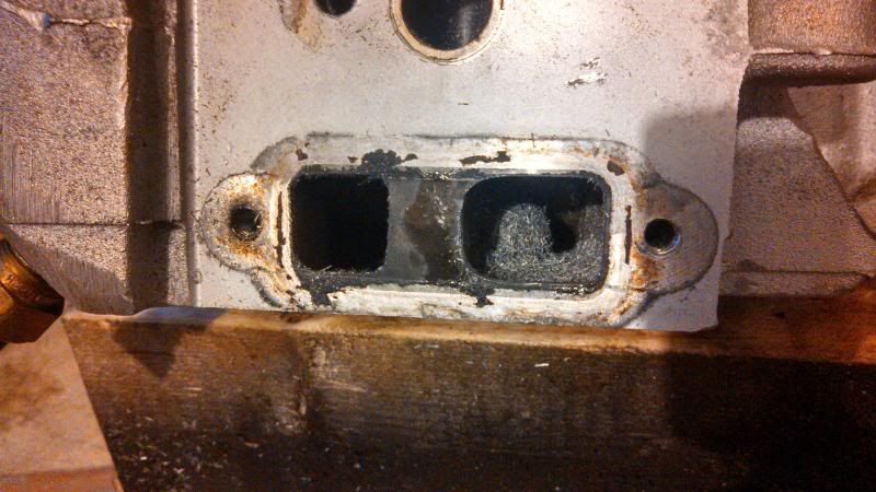
*Left side untouched, right side ported open.*
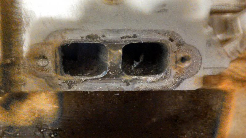
*both sides opened up. *
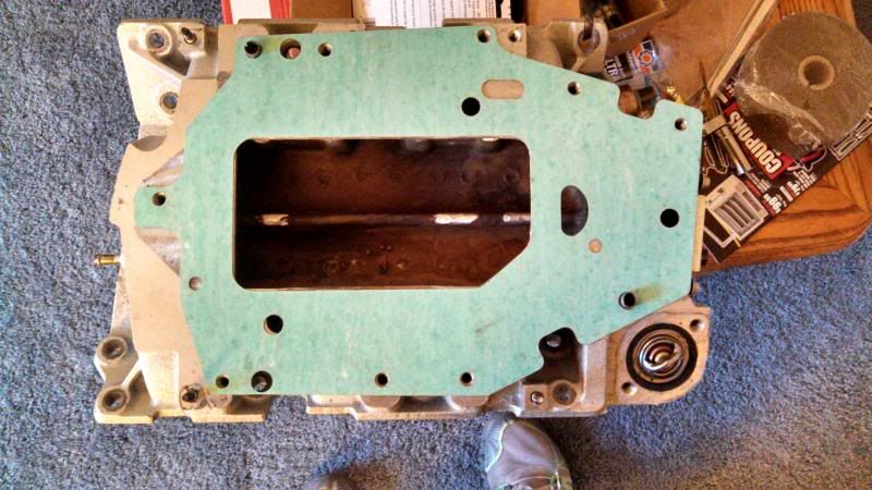
Block your coolant passages. I used JB weld and 2 dimes (has worked like a charm) thought some people only used Quiksteel, and other tap the LIM and use an insert to block them.
Now lay the supplied gasket ontop of the LIM and use a marker to outline the inside edge of the intake area
Use your favorite means to cut the LIM open as showed. I used a dremel with 2 cutoff wheels, and a flapper wheel to smooth the edges.
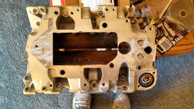
*Some people cut that sliver out between the BBV area and the intake area. I decided to leave it for a cleaner look and less sharp edges*
Now clean the LIM free of all metal dust/shavings. I used high pressure water to get the majority out, followed by a copious amount of WD-40 to help lift any metal flakes. Rinse again and use 1-2 cans of brake-cleaner to get any last trace amounts of metal, oil, and water out.
Time to move on to the supercharger.
*The removal of the H bar in the supercharger case is done to increase the surface area for the air leaving the supercharger into the LIM for better cooling purposes
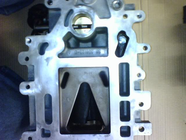
*Stock Gen V outlet, note the large "H-bar" separating the outlet area from the large "pocket" area*
We need to grind that bar down. Using a lathe to mill the bar is the best answer, but for those true DIY guys, a Dremel will work.
*I used a dremel, many cutoff wheels, carbide cutting bits, sanding bits, and a flapper wheel. This took about 3 hours all together (stopping every 5 minutes or so to let the Dremel cool down)
Either tape everything off extremely well so no shaving can enter the supercharger in any way shape or form, or disassemble the supercharger.
*If anyone is crazy enough to use a dremel, feel free to PM me with any questions about this process*
This is what we want to end with.
THIS IS OPTIONAL
I decided to block the silencer ports to get added supercharger whine. DO THIS AT YOUR OWN RISK. Some people swear by it, some people think it's absolutely stupid.
All I did was clean the silencer ports well with brake cleaner and a hard bristle brush. Follow the instructions on the Quiksteel (dont use JB Weld) and cover the ports. Within 10 minutes it will be rock hard.
*You can see how much I used in the above picture of the H-bar delete*
Time to reinstall!
Remove the old LIM gaskets and clean the heads/block. Install your new metal LIM gaskets, using a glob of RTV at the 4 corners where the orange side gaskets meet the aluminum gaskets
Set your LIM back on and start each bolt.
Torque each bolt in sequence to 11ft lbs
*Number 5 is located directly below number 11
Another view

*Some people only use the supplied gaskets, some only use RTV, some use a combination of the two. I perfer straight RTV*
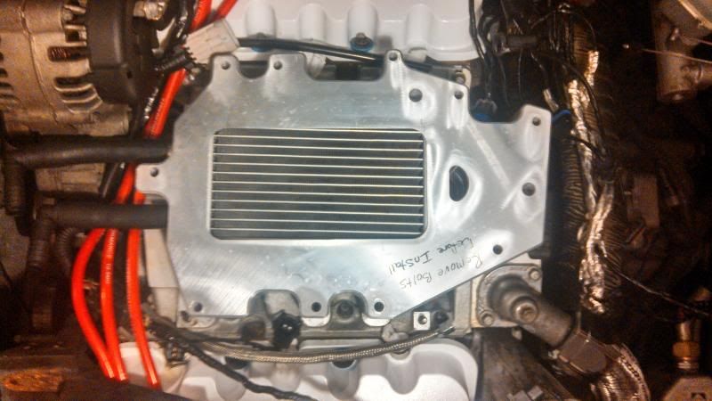
Now it's time to get you Intercooler core on. I suggest that you put it on "dry" (as in no RTV) so you can see how it is going to fit. Once you are ready, go ahead an put some high temp RTV (I perfer the Ultra Copper by Permatex) along the edges of the LIM as seen in the picture.
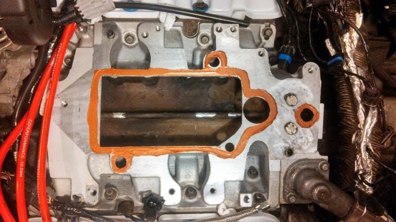
*I like to spread the RTV out slightly as shown so that you dont end up with part of it going inside the intake area*
Now set your intercooler core down on the LIM and make sure it is properly seated against the LIM
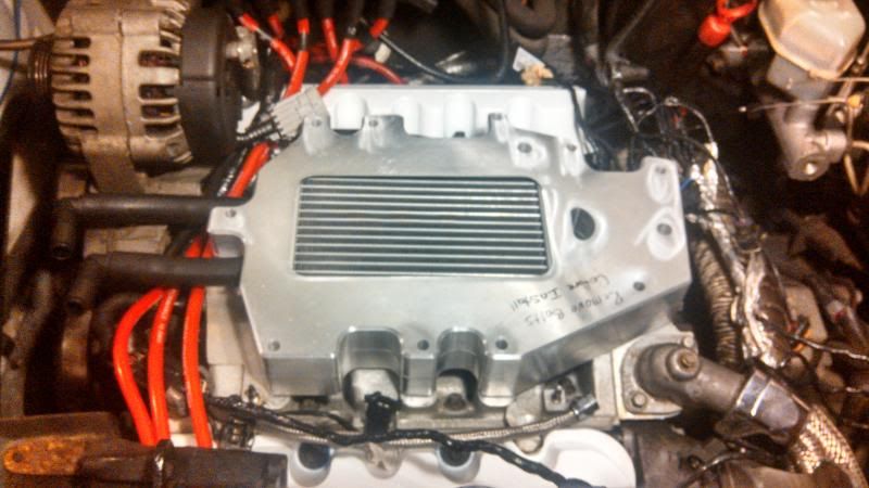
Now we are going to RTV the supercharger to seal it to the IC core.
*Follow this pattern. Yes the EGR is deleted and the front PCV is blocked, but to help ensure that the supercharger completely seals I put RTV around them*
Set your supercharger on the IC core and use a few of the new longer bolts to keep it lined up (it will want to slide around on you)
Start all of the supercharger bolts. Torque them in to 17ft lbs.
I've found that 1/2 torquing them in one pass, then full torquing them works best
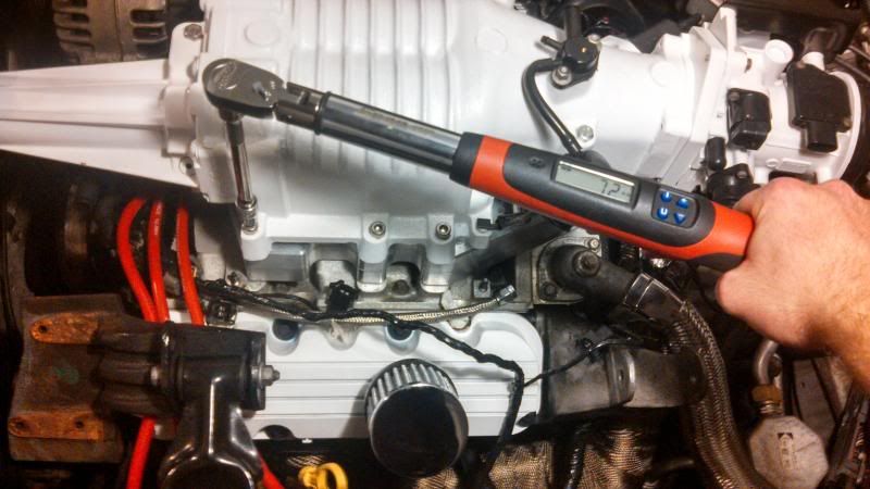
Once you've torqued all the S/C bolts, spin the blower by hand. It should spin freely. If there is any resistance, loosen the bolts and retorque.
Now install your new fuel rails (or fuel logs) and plug all the electrical connectors back in.
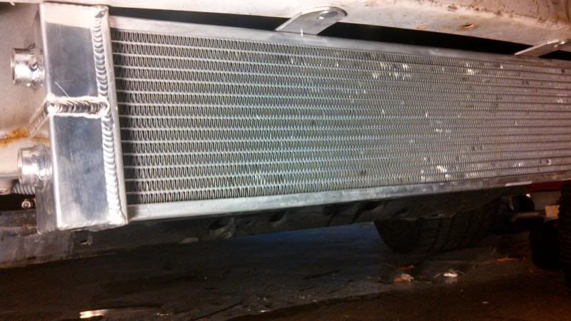
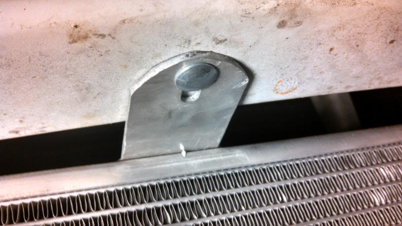
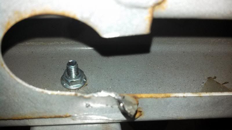
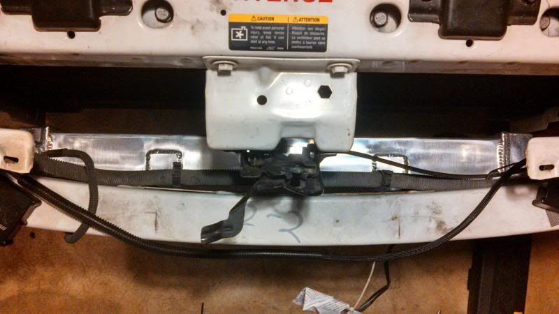
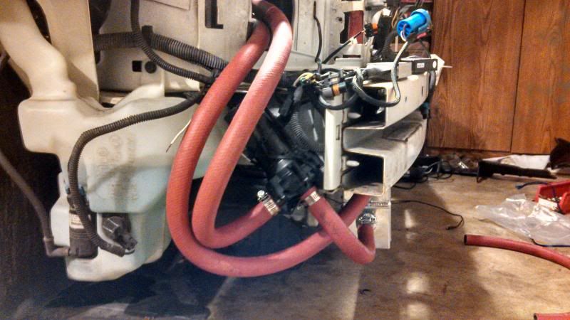
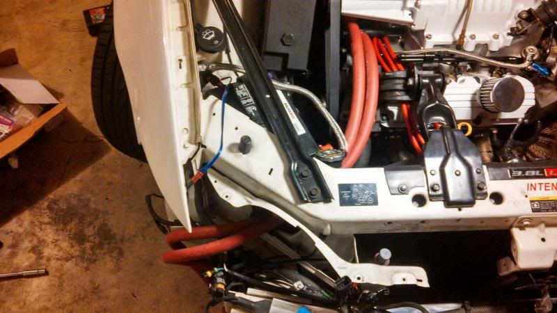
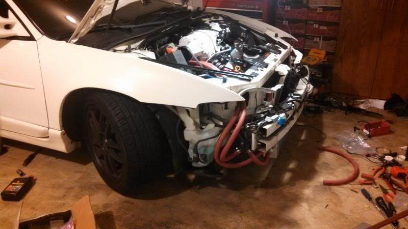
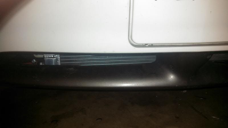
Time for the Front Mount Heat Exchanger (FHME) installation!
First and foremost use common sense and don't skimp out or use short cuts.
Secondly, any modifications that took place I did as I deemed fit, you may decide to route your hoses a different way, not cut a piece that I did, etc. This write-up is to give a good insight on your own install. This was done on a 2002 GTP so your car may be different (GT's that are topswapped, 04+ etc)
So lets hop to it shall we?
Here is your Intercooler kit (the cores are known to be different, fret not they should all still install the same way)
First things first, disconnect your battery.
We're going to need to get the LIM out, so check out any write-ups or this video for more detailed steps.
You will need to remove your intake from the throttlebody
You will need to remove all the electrical connections on the top end of the motor to get the wiring harness out of the way.
You will need to remove both the supercharger belt, and the accessory belt.
*both are 15mm
You will need to remove the vacuum lines from the fuel rail, LIM, and Map sensor.
You will need to remove the fuel rail (Stock fuel rail cannot be used on a fullsize intercooler install unless it is modified) and have some sort of intercooler compatible fuel rail to install in place of the stock rails
Be sure to bleed any pressure off before disconnecting the fuel rail, and have rags handy to catch the fuel that will spill out.
*Some people will simply unbolt the fuel rail from the LIM and leave the fuel lines connected and pull it out of the way. I do not do this as there is the chance to damage an injector, or possibly crack/break the fuel lines*
*Fuel rail removed, most electrical connections disconnected, belts off*
Once you have everything clear of the supercharger, remove all of the bolts holding the supercharger to the LIM. None of the bolts will be reused.
Make sure you have a good surface to set the supercharger on (a large piece of cardboard works great)
Go ahead and lift the supercharger off of the LIM. There should be little resistance, if any is felt, ensure you have all the bolts removed.
*disregard the changing colors of stuff, pics were taken at different times*
Now that the supercharger is clear, you need to pull the LIM off (either to replace it with a ported LIM from a vendor, or so that we can port our own LIM) You will need to drain some coolant so that you dont get any into the lifter valley. I have personally found it the easiest to loosen the lower radiator hose from the water pump, and let it pour out there, this way you are not emptying the radiator and loosing more coolant.
Once you have the coolant below the level of the LIM, we can go ahead and pull it. Either remove the hose from the T-stat housing, or unbolt the T-stat housing from the LIM and move the hose/housing out of the way.
Remove the alternator
Remove the alternator mount/accessory belt tensioner
Remove the EGR from the LIM
Remove all the bolts for the LIM
*not my image, using this as reference for the bolts that need to be removed*
Remove the LIM keeping it as level as possible to reduce the amount of coolant spilled into the lifter valley.
*You may need to tap the LIM up with a soft faced hammer, but usually a quick upward lift will suffice*
Use something to cover the lifter valley so that you get no foreign materials in there. Paper-towels or a large rag work well.
Time to modify the LIM so that we get the most surface area for the intercooler core, and get better coolant flow between the back and front heads.
Remove the 2 8mm bolts from the coolant end cap.
Only port the insides of the coolant passage, not the outer edges.
*Left side untouched, right side ported open.*
*both sides opened up. *
Block your coolant passages. I used JB weld and 2 dimes (has worked like a charm) thought some people only used Quiksteel, and other tap the LIM and use an insert to block them.
Now lay the supplied gasket ontop of the LIM and use a marker to outline the inside edge of the intake area
Use your favorite means to cut the LIM open as showed. I used a dremel with 2 cutoff wheels, and a flapper wheel to smooth the edges.
*Some people cut that sliver out between the BBV area and the intake area. I decided to leave it for a cleaner look and less sharp edges*
Now clean the LIM free of all metal dust/shavings. I used high pressure water to get the majority out, followed by a copious amount of WD-40 to help lift any metal flakes. Rinse again and use 1-2 cans of brake-cleaner to get any last trace amounts of metal, oil, and water out.
Time to move on to the supercharger.
*The removal of the H bar in the supercharger case is done to increase the surface area for the air leaving the supercharger into the LIM for better cooling purposes
*Stock Gen V outlet, note the large "H-bar" separating the outlet area from the large "pocket" area*
We need to grind that bar down. Using a lathe to mill the bar is the best answer, but for those true DIY guys, a Dremel will work.
*I used a dremel, many cutoff wheels, carbide cutting bits, sanding bits, and a flapper wheel. This took about 3 hours all together (stopping every 5 minutes or so to let the Dremel cool down)
Either tape everything off extremely well so no shaving can enter the supercharger in any way shape or form, or disassemble the supercharger.
*If anyone is crazy enough to use a dremel, feel free to PM me with any questions about this process*
This is what we want to end with.
THIS IS OPTIONAL
I decided to block the silencer ports to get added supercharger whine. DO THIS AT YOUR OWN RISK. Some people swear by it, some people think it's absolutely stupid.
All I did was clean the silencer ports well with brake cleaner and a hard bristle brush. Follow the instructions on the Quiksteel (dont use JB Weld) and cover the ports. Within 10 minutes it will be rock hard.
*You can see how much I used in the above picture of the H-bar delete*
Time to reinstall!
Remove the old LIM gaskets and clean the heads/block. Install your new metal LIM gaskets, using a glob of RTV at the 4 corners where the orange side gaskets meet the aluminum gaskets
Set your LIM back on and start each bolt.
Torque each bolt in sequence to 11ft lbs
*Number 5 is located directly below number 11
Another view
*Some people only use the supplied gaskets, some only use RTV, some use a combination of the two. I perfer straight RTV*
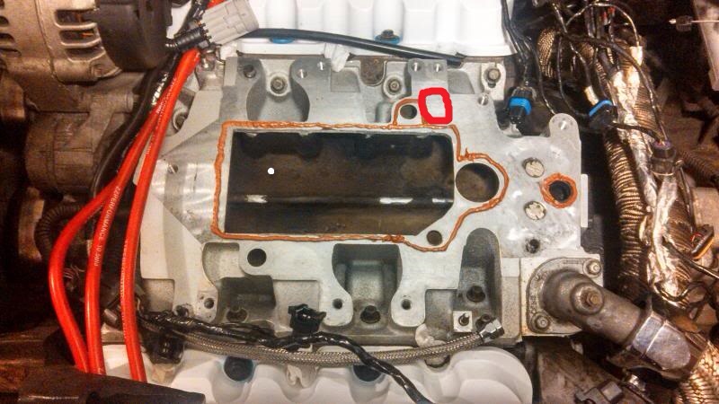
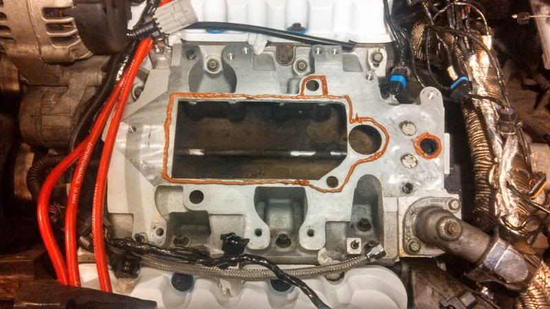
Now it's time to get you Intercooler core on. I suggest that you put it on "dry" (as in no RTV) so you can see how it is going to fit. Once you are ready, go ahead an put some high temp RTV (I perfer the Ultra Copper by Permatex) along the edges of the LIM as seen in the picture.
*I like to spread the RTV out slightly as shown so that you dont end up with part of it going inside the intake area*
Now set your intercooler core down on the LIM and make sure it is properly seated against the LIM
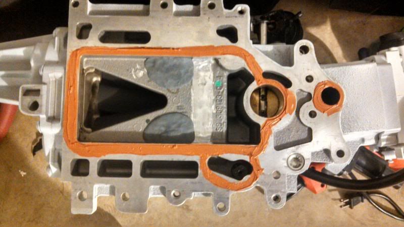
Now we are going to RTV the supercharger to seal it to the IC core.
*Follow this pattern. Yes the EGR is deleted and the front PCV is blocked, but to help ensure that the supercharger completely seals I put RTV around them*
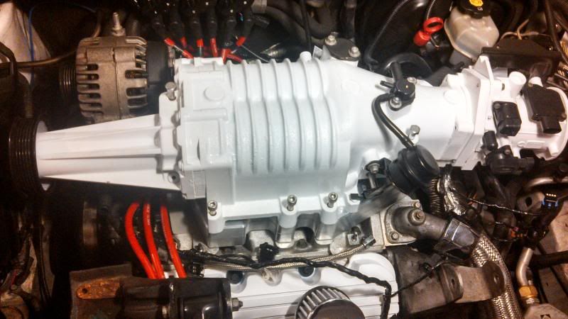
Set your supercharger on the IC core and use a few of the new longer bolts to keep it lined up (it will want to slide around on you)
Start all of the supercharger bolts. Torque them in to 17ft lbs.
I've found that 1/2 torquing them in one pass, then full torquing them works best
Once you've torqued all the S/C bolts, spin the blower by hand. It should spin freely. If there is any resistance, loosen the bolts and retorque.
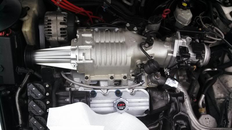
Now install your new fuel rails (or fuel logs) and plug all the electrical connectors back in.
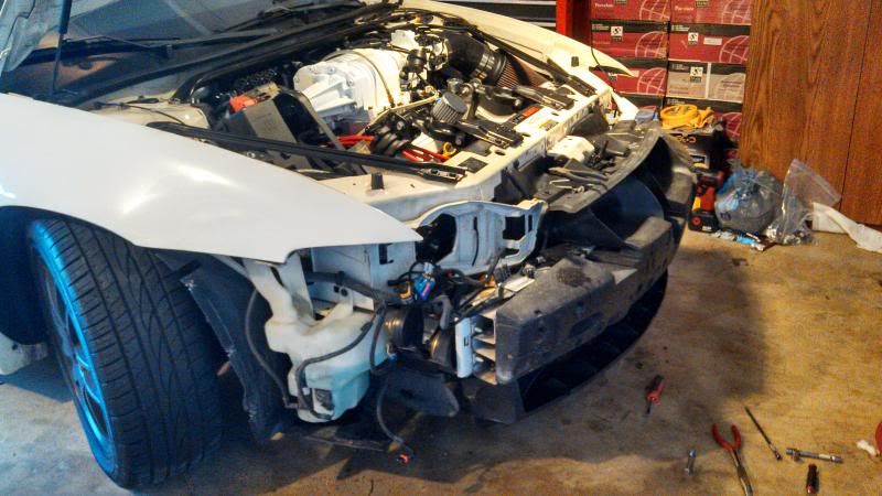
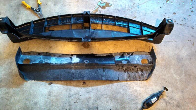
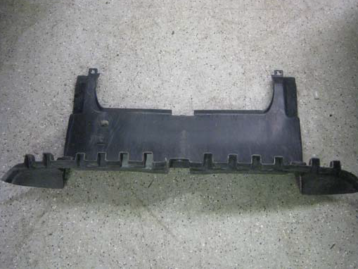
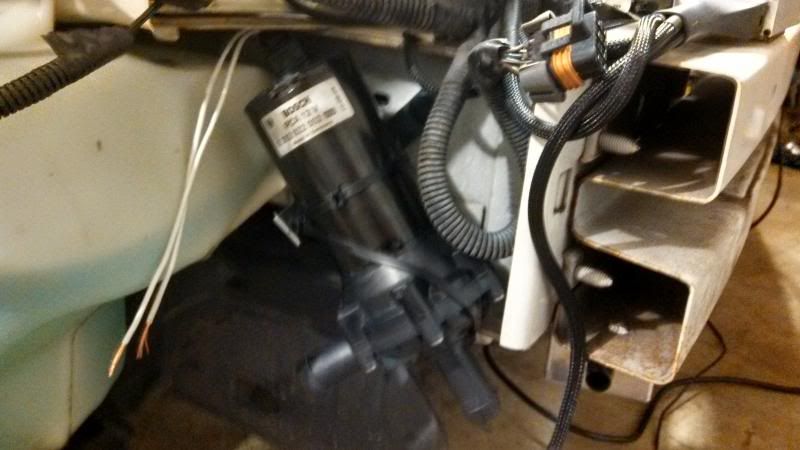
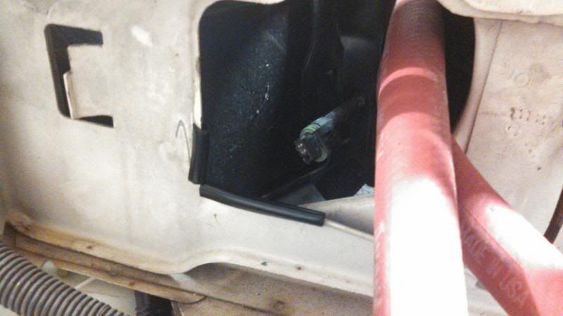
Time for the Front Mount Heat Exchanger (FHME) installation!

")