You are using an out of date browser. It may not display this or other websites correctly.
You should upgrade or use an alternative browser.
You should upgrade or use an alternative browser.
wiring schematic for 3rd brake light
- Thread starter fst
- Start date
 :th_winking:. thansk in advance.
SyntheticShield
New member
Ummm, I'll see if I can dig it up and post..
SyntheticShield
New member
If this is not what you need, let me know and I'll see what I can dig up

SyntheticShield
New member
Thats the way I read it. Its an orange wire from the fuse to the brake switch. The other side of the switch its white to a splice point 'S205', and it continues as white from there to the brake light, or the third brake light or the center high mounted brake like as they like to call it.
Then on the other side of the bulb, its black. It goes to splice point 'S406', one of those two wires goes to chasis ground G302, then the other black wire goes to connector C400 on Pin A. From there it goes through a grommet 'P400' then to splice point S402. Im not sure what that is in the dotted lines unless is the dash turn signal bulb or something, but it changes wire color on the other side of that to Green and then goes through a couple of connectors to the turn siganal switch on the steering column.
Now if you need the location of those splice points and grommets and connectors, just let me know, I believe I have the diagrams for that as well.
yes please on the diagrams ^_^. last thing i want is see sparks ignite, and i know i'd need a multimeter b4 i go connecting and tapping wires lol
edit.....looks like i'd want to finds G302 for the ground and C400 or S402 for the power wire(looks like it goes into the one tail light)
edit.....looks like i'd want to finds G302 for the ground and C400 or S402 for the power wire(looks like it goes into the one tail light)
SyntheticShield
New member
Most of the splice information I have is in textual form rather than diagrams, so I'll give you this:
S402
(CKT 350) Rear lamp wiring harness, behind the right taillamp, approximately 4 cm (2 in) from the right tail/stop/turn signal lamp breakout
G302
(CKT 350) Right door sill, forward of the right front seat
I didnt see in anything that I have that indicated the location of C400, but I'll keep looking and I did find something else that may be of assistance. I'll post it up as soon as I get it on my picture account.
SyntheticShield
New member
C400
(6 cavities) Body wiring harness to the rear lamp wiring harness, behind the trim at the
right rear corner of the rear compartment
(6 cavities) Body wiring harness to the rear lamp wiring harness, behind the trim at the
right rear corner of the rear compartment
SyntheticShield
New member
S402 is the 12v power correct? if so, the only other wire is a ground source, can i just ground the wire from the LED to a chassis bolt somewhere?
No, S402 is a ground splice. S205 is the 12v power source splice that is only active when the brake is used or more specifically, the brake switch activated.
SyntheticShield
New member
Maybe this will help a little too.

SyntheticShield
New member
Well in reality you can ground the thing anywhere to the body of the car since the whole chasis is at ground potential. So as long as its a point that isnt covered by paint or something like that, then you can ground it anywhere. Then tap the white wire in the connector to the third brake light and you should be good to go.
Now, that said, that LED brake light is probably not going to handle 12v very long, so make dang sure that there is some current limiting device that is part of the LED light you have.
Now, that said, that LED brake light is probably not going to handle 12v very long, so make dang sure that there is some current limiting device that is part of the LED light you have.
SyntheticShield
New member
I got a quick and easy solution for ya. Just pack that thing up and send it to me, LOL. I'll wire it in on my car and show you how it works and then you can get another and copy what I did.
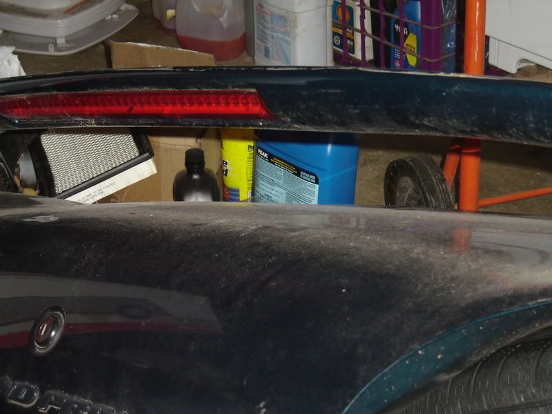
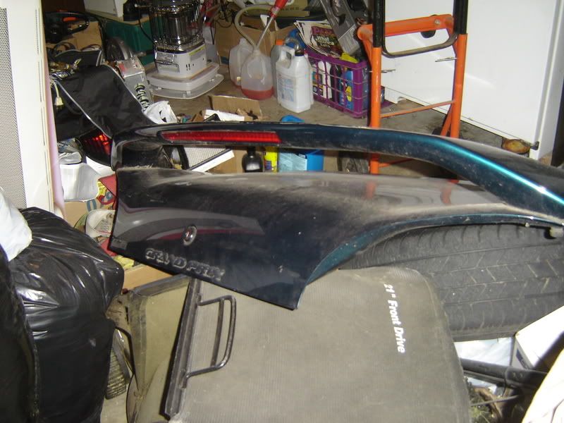
You are likely going to have to extend the wiring from the LED down into the trunk area and obviously make it long enough that it will not bind or anything like that when the trunk lid is open. But once you do that, you'll be able to ground it somewhere to the body/chasis in the trunk and then either connect the 12v source to the third brake light or even the tail lights for that matter.
How you will pass the wiring from the spoiler to through the trunk lid Im not sure, I would assume that there is a hole or something that you could use. I would assume the LED brake light has some current limiting designed into it but I dont know that for sure. If its an aftermarket or factory set up from another vehicle or something, I would hope they have the current limiting built into it.
SyntheticShield
New member
I thought I seen that thing before. I wanted it but Im doing all I can to get out of debt and just a couple months from being there. Additionally, I wasnt sure how that sucker was going to mount up and how I would get the existing holes that are drilled, fixed.