Building a splitter that actually works as a splitter & is an enhancement to the NACA duct Ram air function took some engineering & work! Plus wanting it to enhance the overall front end look! This final design developed over about a 8 month period.
First of all I wanted a splitter that would add to the look of the front end! What does that mean? Well some, or all may not agree with me, but, while I love the throwback to the muscle car coke bottle shape of the 7th Gen GP. I have stated before that I always felt that the front nose, especially from the side view looks weak! Why? Well, my opinion is the front nose from the side comes to a point just above the license plate cover. This is enhanced by a stock hood which has a forward slope , then a sharper angle of the cover at the grille area. A short flat area at the license plate cover & then a step back angle below that. This makes a noticeably progressively smaller, top to bottom appearance as you move away from the windshield to the front nose.
I wanted to beef up the look of the front nose, I.E. make the nose look less slopped & more blunt as opposed to pointed. While removing as much as possible the slopped look of the hood towards the nose design.
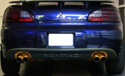
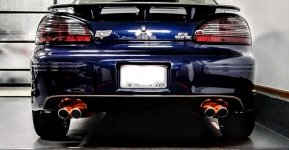
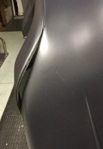
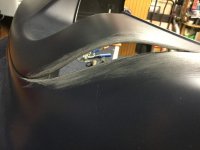
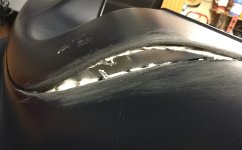
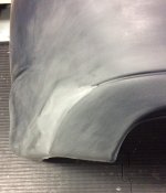
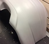
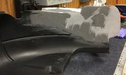
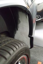
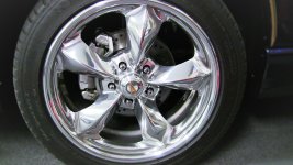
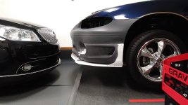
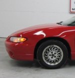
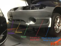
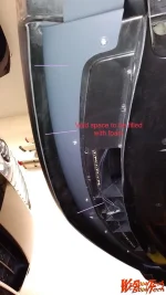
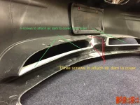
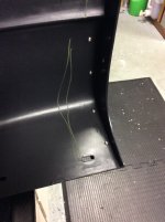
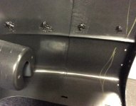
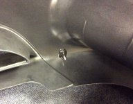
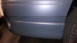
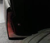
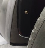
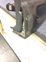
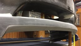
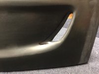
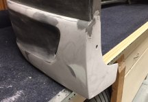
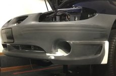
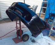
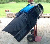
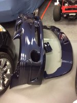
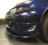
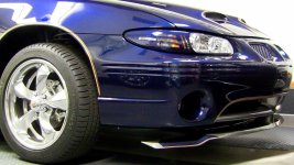
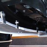
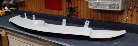
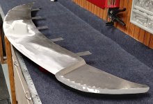
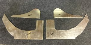
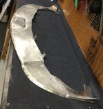
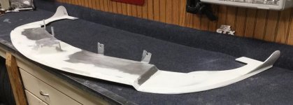
So that first step was the F.1 MPD hood. Because this hood visually tends to raise the front profile of the hood. Then the SD air dam. This piece pushes the lower portion of the front cover out forward, giving the side profile a more blunt look, as well as beefier one. All this was stated before. But I still wanted a little more blunt appearance & less roll at the very bottom of the cover. So the splitter needed to be that piece! Plus perform as a splitter & enhance the NACA duct! Notice that the first picture is with the stock front cover & the first splitter I made. The next two are with the addition of the SD air dam & the second splitter I made, which was modified to become the final splitter used. Notice in the 4th picture there is an overall appearance of a more blunt front.