• The site migration is complete! Hopefully everything transferred properly from the multiple decades old software we were using before. If you notice any issues please let me know, thanks! Also, I'm still working on things like chatbox, etc so hopefully those will be working in the next week or two.

The Last American Indian an FWD Ground Pounder

The Last American Indian

The “97”-“03” Grand Prix (MS2000) platform, under the GM-10 umbrella. This was the last America designed & built Pontiac! The W-body l was designed in Canada & some parts was built there. The W-body lll was a redesign of the MS2000 platform. It was once again designed in Canada & much of the car was built in Canada!

A little back history to explain The Last Indian’s progression.
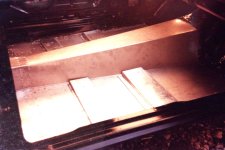
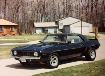
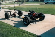
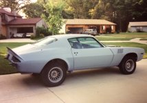
I’m not that guy that does car shows. So I just do cars for me! To please me! For the pleasure of seeing an idea live! But in 1984 a Swedish magazine, (Start & Speed) was here in the Cleveland area and was told of my custom 1969 Z/28 by a friend of a friend. They approached me for a cover piece so I allowed it. Most of the car was custom designed and handmade, including the full frame with an OEM suspension front and rear, not coil overs in the back like you often see with full frame conversions, but it was so much more than that! For a myriad of reasons I sold it and a “74” Z/28 that was custom as well in 2004 after 35 and 30 years of ownership!
I had bought a brand new 2000 Pontiac Grand Prix, so after selling the Camaros I decided to take the GP for a summer only car and for a FWD it wasn’t bad. It wasn’t good mind you, but I did love the updated Coke bottle shape and styling. So I thought I was done modifying & customizing cars after 36 years of doing so!

I was just going to drive it. I had done a lot with cars at multiple levels, maybe it was time to refocus on something new, not sure what, maybe bird watching? Well the boredom lasted a year! So I embarked on a new path, a path that I didn’t know would become that of The Last American Indian! With the “97”-“03” Grand Prix being the last American designed & built Pontiac and the end of Pontiac as a car company occurring just a few short years later!
I had always owned RWD cars until the GP, but I found myself realizing all I had ever seen anyone do with a FWD, was either cosmetic things or on the engineering side, power or drifting. Yet no true performance handling, no true blend of drivetrain performance, handling and style! Especially not in an American car and not in the vein of the old muscle car era ground pounders and most assuredly not performance handling. I remember when the first gen Camaro was called the poor man’s Porsche and that was what inspired me to make mine better than a Porsche. Why not a similar mind set with FWD I thought? Drifting isn’t powering thru a corner and it certainly isn’t handling, so l thought, try something different!

Stay tuned! This is a build you will want to see if you love the W-body ll!
 
Last edited:


So a quick overview of the two Camaro’s as a point of what can be done, even to the extent of the W-body ll.
Putting full frames under these cars, while utilizing the rear leaf spring suspension transforms the characteristics of the entire mathematical physics, relative to ground adhesion & lateral G force. The process lowered CG & RC, but had a more dramatic impact on RC. It also altered weight distribution.
 

Attachments

  • FullSizeRender 12.jpeg
    FullSizeRender 12.jpeg
    802.7 KB · Views: 0
  • FullSizeRender 10.jpeg
    FullSizeRender 10.jpeg
    628.7 KB · Views: 0
  • FullSizeRender 11.jpeg
    FullSizeRender 11.jpeg
    659.4 KB · Views: 0
  • FullSizeRender 9.jpeg
    FullSizeRender 9.jpeg
    560.4 KB · Views: 0
  • FullSizeRender 8.jpeg
    FullSizeRender 8.jpeg
    653.5 KB · Views: 0
  • FullSizeRender 7.jpeg
    FullSizeRender 7.jpeg
    651.7 KB · Views: 1
  • FullSizeRender 4.jpeg
    FullSizeRender 4.jpeg
    968.6 KB · Views: 1
  • Swkfprb1-1012121914040.jpeg
    Swkfprb1-1012121914040.jpeg
    280.5 KB · Views: 1
  • FullSizeRender 29.jpeg
    FullSizeRender 29.jpeg
    639.7 KB · Views: 0
  • FullSizeRender 24.jpeg
    FullSizeRender 24.jpeg
    939.9 KB · Views: 0
The very first thing I wanted to address was handling! This platform (MS2000) possesses all the attributes it needs to become a great handling car. I looked at all the math that applied to the physical perimeters of the platform. It has the ability to achieve at the very least 1.1 G’s in a 300’ skid pad test. But a skid pad test is only a small indicator of handling performance. Yes, 300’ skid pads & tight turns are heavily affected by yaw, which is a fundamental part of handling, but abrupt 90 degree turns, aka hard cornering are actually more affected by yaw than those types of turns & they are what truly defines a great handling car! I am talking about making a 15’ to 20’ hard right turn onto a side street at 15-17 mph! Or like autoslalom racing or road courses.

So first on the agenda was to change the CG, the RC & weight distribution! These three things become the cornerstone of which everything else is based on.

Remember this, lowering a car by changing springs affects CG, but, and it is important to remember, it has little to no effect on RC! What it does do is negatively impact suspension travel & as such suspension response! Yes, because the CG is lower than it was, the vehicle feels more stable, corners tighter! But if put to the test it will fail at true maneuverability! Not to mention those ground clearance issues.

So my very first task was to change the structural stiffness of the car. Creating an even better, more dynamic resonance phenomenon! In stiffening the frame/unibody structure with a two part structural urethane foam. Notice in the pictures there are no open cavities left. You will notice that all the metal expansion holes that are found in the floor & rail stampings are gone.
 

Attachments

  • front subframe sec.jpeg
    front subframe sec.jpeg
    151 KB · Views: 1
  • undercarriage.jpeg
    undercarriage.jpeg
    357.8 KB · Views: 1
  • IMG_0151.jpeg
    IMG_0151.jpeg
    811.4 KB · Views: 1
  • IMG_0237.jpeg
    IMG_0237.jpeg
    821 KB · Views: 1
At the same time I needed to look at current perimeters of the indian, (SSF) static stability factor (1.4), weight distribution(65/35), CG(20”), RC(67”), wheel base(110.5), track width ft.(61.7) rr.(61.1) these are key components of the suspension geometry that will need to be changed. These numbers are not very good for a car that you want to handle, but they're pretty normal for FWD though.

After initial modifications those numbers changed to the following, (SSF)(1.68), weight distribution (54/46), CG(16”), RC(51”), wheelbase(same), track width ft.(64.5”), rr.(64.5”) for comparison of suspension geometry above after modifications.

So without getting too technical & lengthy, it goes like this. To effectively increase handling you must lower the CG & reduce the RC & get the weight distribution as close to 50/50 as possible, if that applies, and it did here.

The first choice by most people to lower CG is to use lowering springs/struts. That should not be the first choice, but the last! There are many ways to lower CG without lowering your car & those ways are actually more effective.

How I lowered the CG! So the first thing you would always prefer is to lighten the car where needed, but when you can’t you move the weight around and where necessary you add some, thus was the case here. Then you look to increase the track widths & last modify the suspension components to take advantage of those changes.
 

Attachments

  • IMG_0151.jpeg
    IMG_0151.jpeg
    811.4 KB · Views: 0
  • P1010129.jpeg
    P1010129.jpeg
    742.3 KB · Views: 0
  • P1010128.jpeg
    P1010128.jpeg
    942.6 KB · Views: 0
How I lowered the CG! So the first thing you would always prefer is to lighten the car where needed, but when you can’t you move the weight around and where necessary you add some, thus was the case here. Then you look to increase the track widths & last modify the suspension components to take advantage of those changes.

In the end approximately an equivalent of 300 lbs was added to the rear weight of the Indian and all but 15lbs. of it was below wheel centerline. That is very important, for both CG & RC! The equivalent of 80lbs was removed from the front nose area and relocated to the rear of the car, again below wheel centerline. 30 lbs was added to the rear impact bar. Part of the weight redistribution was the relocation of the battery to the trunk spare tire well. Additionally the entire frame structure and dead spaces (lower firewall & rear cavity structure, control arm area) were filled with structural urethane foam, contributing 22 lbs of the 300. The rear suspension carrier was reinforced to reduce flex in hard cornering, extra large lateral bars & trailing arms were installed. There was a redesign of the upper rear strut mounts. As well as the front lower A-arms to reduce torque steer and increase power transfer to the ground.

Front struts components were redesigned for increased corner stability & power transfer through better spring function. Heavy duty police package springs front & rear were installed. Upper strut bearings were replaced with industrial grade pieces for better responsiveness and smoother wheel control & stability.
 

Attachments

  • IMG_0155.jpeg
    IMG_0155.jpeg
    677.8 KB · Views: 0
  • IMG_0393.jpeg
    IMG_0393.jpeg
    747.4 KB · Views: 0
  • IMG_0161.jpeg
    IMG_0161.jpeg
    350.6 KB · Views: 0
  • IMG_0160.jpeg
    IMG_0160.jpeg
    335.6 KB · Views: 0
  • IMG_0156.jpeg
    IMG_0156.jpeg
    740 KB · Views: 0
  • P7140375.jpeg
    P7140375.jpeg
    986.3 KB · Views: 0


Part of the weight redistribution was the relocation of the battery to the trunk spare tire well. The rear suspension carrier was reinforced to reduce flex in hard cornering, extra large lateral bars & trailing arms were installed. ZZP sells a tubular rear carrier, but while they claim it reduces flex it will not reduce flex like the OEM with the gusseting you see here! This carrier doesn’t just reduce it; it eliminates it completely.
The front lower A-arms modification is a substantial improvement, it reduces torque steer and increase power transfer to the ground. This similar to ZZP tubular A-arm, but much stronger as the welded structure will not twist or flex.
 

Attachments

  • IMG_0159.jpeg
    IMG_0159.jpeg
    644.4 KB · Views: 1
  • IMG_0490.jpeg
    IMG_0490.jpeg
    861.3 KB · Views: 0
  • IMG_0157.jpeg
    IMG_0157.jpeg
    329.5 KB · Views: 1
  • IMG_0178.jpeg
    IMG_0178.jpeg
    818.6 KB · Views: 1
Again, front struts components were redesigned for increased corner stability & power transfer through better spring function. Heavy duty police package springs front & rear were installed. Upper strut bearings were replaced with industrial grade pieces for better responsiveness and smoother wheel control & stability.

With respect to the front struts. The upper pieces are of a poor material design. They exist of plastic pieces that retain rubber insulators & plastic thrust bearing races! That’s just stupid! While these may be standard for FWD cars, they have no structural integrity for performance. They degrade the overall ability of the steering action as well as the transfer of energy through the strut/spring as intended! Instead some energy is deflected outward, distorting the action of that energy!

The first picture shows the original upper strut bearing with plastic races (yellow & black). The lower three pieces are the industrial grade thrust bearing (middle) & the two hardened steel races (left & right). The rest are somewhat self explanatory.
 

Attachments

  • IMG_0484.jpeg
    IMG_0484.jpeg
    917.1 KB · Views: 1
  • IMG_0485.jpeg
    IMG_0485.jpeg
    653.1 KB · Views: 1
  • IMG_0486.jpeg
    IMG_0486.jpeg
    931 KB · Views: 0
  • IMG_0488.jpeg
    IMG_0488.jpeg
    859 KB · Views: 1
Last edited:
Both front and rear sway bars and their end links were replaced. The front bar was replaced with a solid 33mm bar from ZZP. Then redesigned, larger, shorter & stiffer end links. The end links are actually what make the sway bar work! If they are weak, then you get a lot of deflection & minimal resistant energy through the bar! So the body rolls anyway! The OEM links use 5/16” by 6” long through bolts with a plastic spacer & buna rubber donuts. My new design uses ⅜ diameter by 3 ½ long bolts. A shorter solid SS spacer with two urethane inner donuts & two nylon short donuts with two jam nuts, with the top nut being pinned! The top nut needed pinned because the links worked so well that repeated hard cornering would cause the nuts to unscrew.

The rear bar was replaced with a solid 25mm diameter bar from ZZP. A new designed set of rear end links were built as well. The OEM end links are a pathetic ¼” or 5/16” diameter, don’t remember anymore, by about 10” long. The new design is built from ¾ diameter female heim joints that are connected by a ¾ SS hex & ½” threaded stock. Overall length is about 7” long.

Both sets of end links make a significant improvement over the OEM units as they make the bars do what they were designed to do, prevent body roll and keep the wheels planted on the ground! All while keeping the ride comfortable.

The third picture is an old one from when it was first put together. Before I started seeing the nuts unscrew. Also the third & forth pictures are before all modifications were made, such as different wheels, A-arm modifications, etc..
 

Attachments

  • IMG_0153.jpeg
    IMG_0153.jpeg
    370.7 KB · Views: 1
  • IMG_0392.jpeg
    IMG_0392.jpeg
    458.5 KB · Views: 1
  • front sway bar link.jpeg
    front sway bar link.jpeg
    54.9 KB · Views: 1
  • rear sway bar hiem joint.jpeg
    rear sway bar hiem joint.jpeg
    157.4 KB · Views: 1
First of all I need to preface this with the edict, that this modification in the project is quite involved! If done in this manner. It will require, if done as described in these instructions, more than one day. & at least the partial removal of the interior.

You will need at least 25 ft. Of 2/0 welding cable for the + side & at least 30 ft. of 1/0 welding cable for the – side. I would recommend you make accurate measurements of both first before you buy, as welding cable is not cheap. You need welding cable because it will deliver the most power with the least loss of amperage over these long runs of cable. This is due to the fine strands of copper wire. Additionally, the welding cable is very flexible, which you will need for this installation. You will also need high quality lugs that will be crimped on to the ends of the cables so you will need a crimper or a means that is big enough to do that. You should also consider heavy gage shrink tube to seal the lug ends to the cable. You’ll need a 300 amp mega fuse & holder that will mount in the trunk area. This is needed for safety, just in case something shorts for any reason! Even an accident could cause this occurrence. That fuse will blow keeping the battery from shorting & causing a fire!

I mounted the battery, which is a Odyssey battery PC925, under the spare tire. This batteries specs are more than sufficient & is the only style that will fit in this manner, which is to have the least amount of impact on the aesthetics of the trunk compartment. This configuration works very well, but requires the removal of the jack & its components, but not the spare. The jack & its components we’ll need stored elsewhere. You will need a battery hold down setup that can be bought at most auto parts stores. The following materials will be approximately the length of the bridge/brace you see below in fig.1 & by a width that will house the battery. So the following will be needed, a 12”x?”x1/2” sheet of nylon, a 12”x?”x1/4” sheet of nylon & a 12”x?”x1/4” sheet of neoprene. These will be used to make the mounting base for the battery. You are going to remove the large styrofoam disc that the spare sits on as well as the threaded shaft assembly that holds the spare down & set them aside for now.

So starting with the trunk mounting setup, I’ll use some pictures (fig. 1) below
 

Attachments

  • IMG_0500.jpeg
    IMG_0500.jpeg
    85.3 KB · Views: 0
This is the bare spare tire area, above. The factory bridge/brace is used as the anchor point for the mounting.

I do not have the dimensions that I used for the nylon plates, but you should be able to determine them based on the pictures that will be provided & the basic spare tire floor configuration & battery footprint. The 12”x?”x1/2 nylon plate should be cut so there are two pieces. One goes on one side of the bridge/brace & the second piece goes on the other side. When cut to their finished size, their combined dimensions, plus the width of the bridge/brace front to back, will determine the dimensions of the upper 12”x?”x1/4”nylon plate. Which will end up the size you determine.


(Fig. 2) below
 

Attachments

  • IMG_0501.jpeg
    IMG_0501.jpeg
    277 KB · Views: 0


In this picture you can see the corresponding screws that attach the assembly to the bridge/brace as shown in fig.1. You can also see that the ½” piece of nylon adjacent to the two rubber knockout plugs is relieved to clear the trunk floor upsets it lays over. What you can’t see is that those two pieces of ½” nylon are attached to the ¼” nylon piece with screws on the underside, so that this becomes a one piece assembly to install.

You also need to drill a clearance hole for the spare tire threaded shaft assembly. Now cut a piece of the neoprene to a dimension that is slightly larger than the battery footprint. Next you need the battery or at least the battery footprint & the spare tire styrofoam. Cut a square out of the center of it, but much smaller than you need & Install the styrofoam back in place using the tire threaded hold down as a locating guide. Lay the neoprene in the styrofoam & center it in the middle. When you are sure it’s where you want it mark the styrofoam for cutting, fig. 4. After cutting the styrofoam mark the nylon like you see in figure 3. Remover the styrofoam & place the neoprene on the nylon as in fig. 3. Referencing to fig. 5 you will see the type of battery hold down I used. Using the top piece of the hold down as a guide, mark where you want the holes for the threaded rod to be used for the hold down. I used 1/4x20 all thread, drilled & tapped the top nylon plate & used a double nut on the backside. You can see I made brass L brackets to use on the battery terminals to keep the profile low. I also needed to carve some of the styrofoam out of the spare tire styrofoam to allow access to those L brackets. Fig. 6 shows the assembly without the clamping bracket in place. Fig. 7 shows the entire assembly with the spare tire styrofoam installed.


(Fig. 3) below
 

Attachments

  • IMG_0502.jpeg
    IMG_0502.jpeg
    260.1 KB · Views: 0
Back
Top