chamilton89
New member
Hey guys,
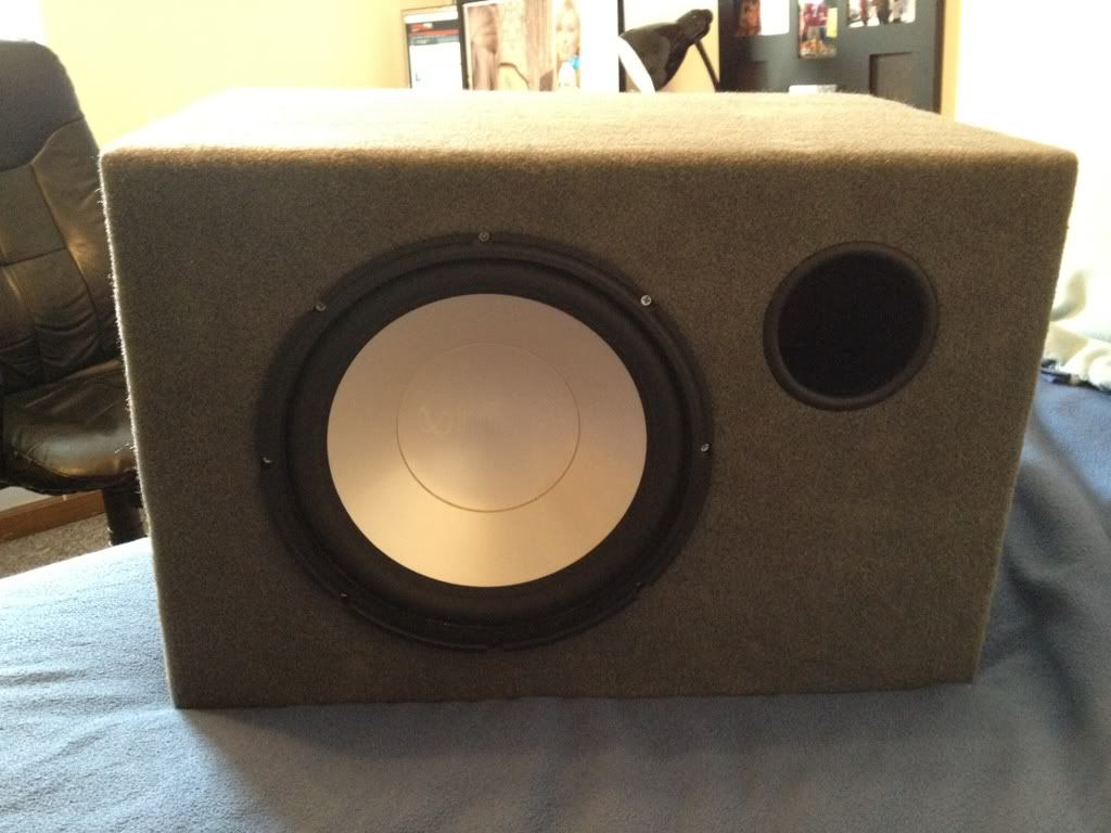
For a few years I've had an extra subwoofer and amplifier laying around that I half assed to work inside my home. This is the third and final iteration of this project, and I think its pretty damn cool. I have a ported infinity reference subwoofer and an infinity amp which I shoe-horned into a custom box I made. This third box is larger than the last and the subwoofer box itself is sealed from the amplifier and power supply. Check out the pictures for more info and tell me what you think!
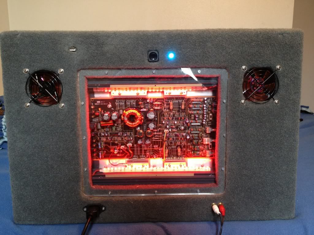
Ardunio controlled fans, Notice the blue LED to signify that the amplifier is on, and the fans are not running.
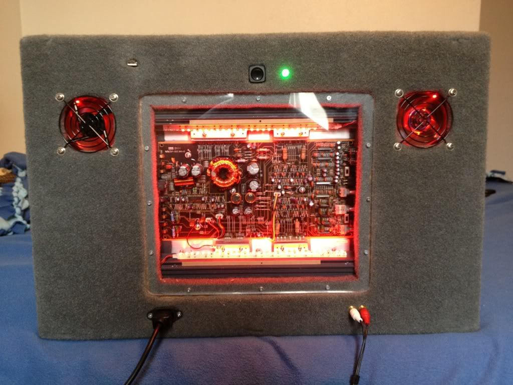
Second picture of the ardunio controlled fans but this time, the thermistor temperature sensor on the heat sink on the power supply has heated up enough to turn the fans on, one exhaust and one intake. They are controlled by the temperature sensor and are variable speed thus, the hotter the power supply gets, the more air the fans push. If and when the fans are needed to run at full power to cool the power supply, the LED turns red. Also note the USB input on the top left, that connects to the onboard arduino that controls the fans. I can do diagnostics and reprogramming remotely.
For anyone who is interested, here is a picture of the completed interior wiring. Notice the computer power supply to convert 120v AC to 12v DC for the amplifier. Also, on the other side of the amplifier is the arduino micro controller hooked up to the fans, and the lights located inside the amplifier housing. The board runs off 5 volts from the computer power supply and takes in a 0-5 volt signal from a thermistor located on the heat sink power supply to control the fan speed and aureately gauge the power supply temperature.
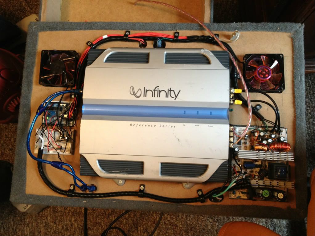
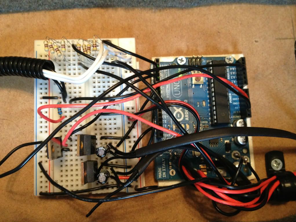
Closeup of the breadboard and arduino circuits. The usb connector on the ardunio has been relocated on the rear of the subwoofer to reprogram and view real time temperatures on the arduino.
For a few years I've had an extra subwoofer and amplifier laying around that I half assed to work inside my home. This is the third and final iteration of this project, and I think its pretty damn cool. I have a ported infinity reference subwoofer and an infinity amp which I shoe-horned into a custom box I made. This third box is larger than the last and the subwoofer box itself is sealed from the amplifier and power supply. Check out the pictures for more info and tell me what you think!
Ardunio controlled fans, Notice the blue LED to signify that the amplifier is on, and the fans are not running.
Second picture of the ardunio controlled fans but this time, the thermistor temperature sensor on the heat sink on the power supply has heated up enough to turn the fans on, one exhaust and one intake. They are controlled by the temperature sensor and are variable speed thus, the hotter the power supply gets, the more air the fans push. If and when the fans are needed to run at full power to cool the power supply, the LED turns red. Also note the USB input on the top left, that connects to the onboard arduino that controls the fans. I can do diagnostics and reprogramming remotely.
For anyone who is interested, here is a picture of the completed interior wiring. Notice the computer power supply to convert 120v AC to 12v DC for the amplifier. Also, on the other side of the amplifier is the arduino micro controller hooked up to the fans, and the lights located inside the amplifier housing. The board runs off 5 volts from the computer power supply and takes in a 0-5 volt signal from a thermistor located on the heat sink power supply to control the fan speed and aureately gauge the power supply temperature.
Closeup of the breadboard and arduino circuits. The usb connector on the ardunio has been relocated on the rear of the subwoofer to reprogram and view real time temperatures on the arduino.