Travisgt2
New member
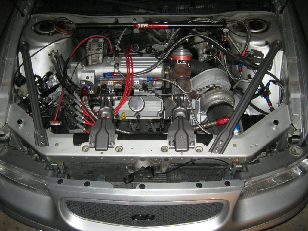
What intake is that?compressor discharge goes downward and curves around the AC drier and between the subframe/radiator support to curve around to the IC inlet
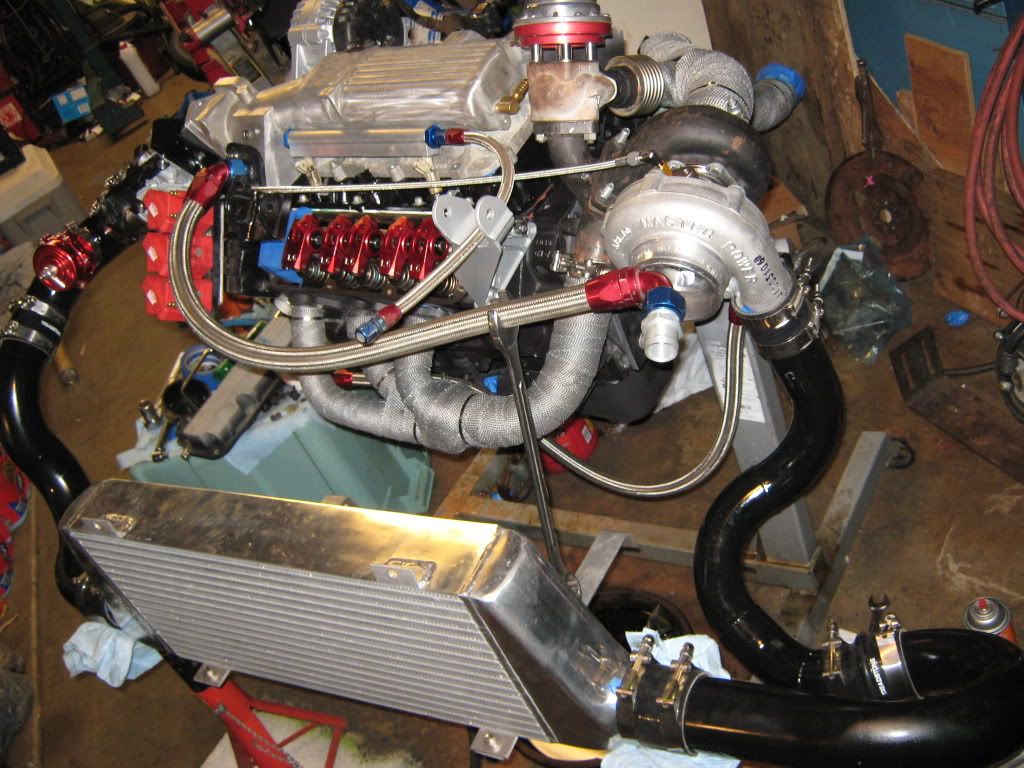
here you can see the 2.5" discharge pipe to 3" connection point and the routing.
the reason is simple, i wanted the battery where it'll do the most good...weight forward and as far below the axle centerline as possible.
a true win win when going to pass TB
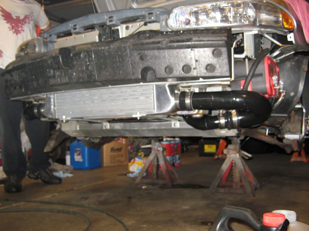
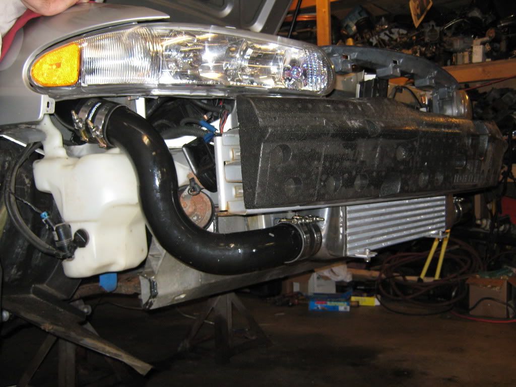
throttle body side follows the usual path up over the washer res and through to the engine bay next to the res fill.
its tight enough that the bumper cover being removed is nice but all clamp and coupler points were laid out and setup so that only the inner tire shield and/or the headlight have to be removed to service either side.
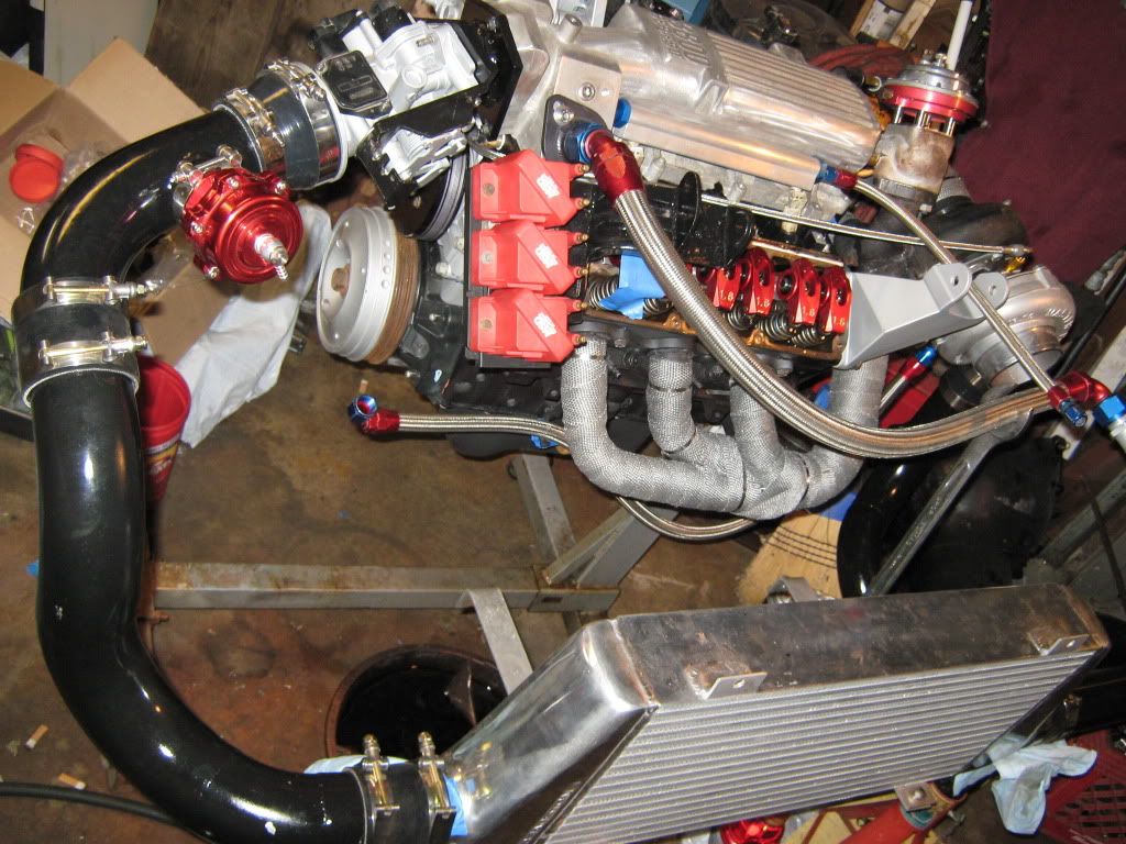
since i had enough foresight to know that i was gonna be doing alot of repair work for the trans... i did setup the car and build so that engine removal is simple. pipes are disconnected and left in-situ and the engine can be pulled with just the removal of the DP. no need to disconnect any turbo plumbing or hotside parts. much less chance of contamination at an oil line if you layout your setup properly.
its not as easy as unzipping my fly but its fantastically more serviceable than many setups.

Sent from my SM-S820L using Tapatalk


