• The site migration is complete! Hopefully everything transferred properly from the multiple decades old software we were using before. If you notice any issues please let me know, thanks! Also, I'm still working on things like chatbox, etc so hopefully those will be working in the next week or two.

LIM Modification

No problem Scotty,To bad no one has access to some kind of flow bench that would work on this.


edl-2921.jpg


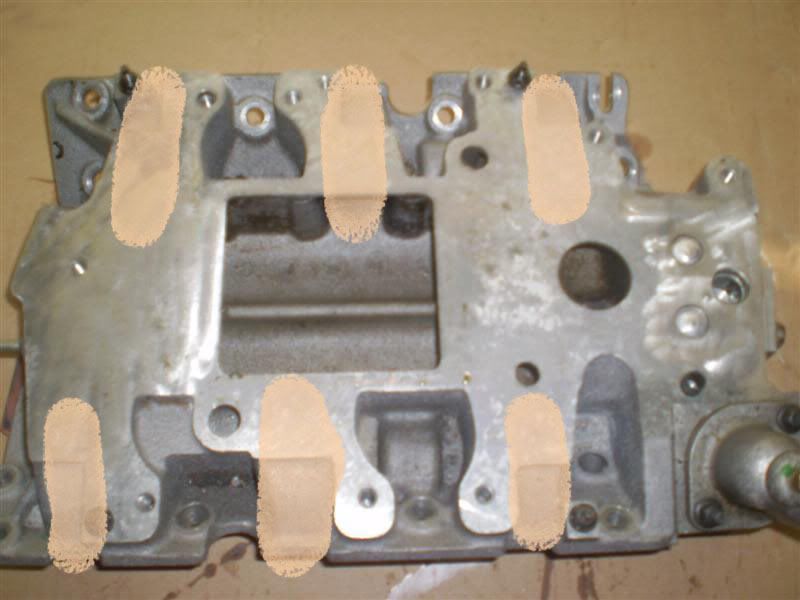
Now this is for a carbed 302 setup. That being said there really is no reserve box to store up air to be used by the runners, but the air is readily availabe from the opening of the buterfly blades of the carb. This I belive is a much more efficent design of how the intake runners are being used/routed.


Just thought i'd share the image of an average aftermarket intake manifold to give some ideas.


i was looking at a pic of a LIM on a eaton cobra and there inlet from the supercharger is also offset to one side and i have heard of the 7 and 8 cylenders going out. so i retract my statement of them being starved. ive seen instenceses where they cut the LIM to make the openen bigger. would that help with the starvation??
 
much like the one zzp has. im sure that would help with starevation. that edelbrock one is nice tho. more of a direct flow. would be nice if we had something like that
 
The opening of the lim in the back is to take advantage of an intercooler. May help with other things though. Not real sure.
 
i am still non intercooled and i have mine cut for an intercooler already (LIM and blower). although it still isnt completely open, i think it helps to some extent. with more area below the blower just to soak up space it helps to keep the outlet temps down slightly. at least i can picture it working that way.


I think Scotty is onto a bigger problem than he thinks, It may seem that cyl 3/6 are out of the way in the LIM, and I had looked at this when I did the Top swap, but it is more complicated than that, I highlited the short runners so you can see them better :

LIM.jpg


As you can see above, cylinder 2/5 are the only ones in direct path from the blower, so 1,3,4,and 6 all are off a bit, which is why I think I may try to play with the injector skew for cylinders 2 and 5......

but then when you look at the blower, you see that most air comes out at the leading edge, which is where cylinder 2 is (the banks are offset about an .5 inch) so cylinder 2 may get more air than all the others...... maybe a runner plate that would just drop in would help????
 
Holy cow, I did not realize they were offset in that manner. I had originally had in the back of my mind if this was perhaps part of the problem with the #3 cylinder popping, but I couldnt draw any reasonable conclusions that if the #3 piston was prone to popping due to this, then why not the others as well, particularly #1, #3, & #5 with the restrictive front exhaust manifold.

Im looking at the drop in runner idea and a couple others. It will take time as I dont have the resources I would like, but I'll get something figured out.
 
Thank you for posting that Lee. You can clearly see the splitter in that image. Im not a big fan of machined LIM's. Even in IC'd applications I have a hard time seeing the point as the outlet on the blower is only so big, however, they work so there is obviously some things there in that application I dont completely grasp or see clearly.

TDC, thank you for posting that manifold too. That is kinda what I wish we had and wish I could adapt a set of runners like that to our manifold. You have to be careful though with the runner design as it plays an important role in where your power band is. Long runners for upper RPM range, short runners for better throttle response and lower end performance. Ive even seen vehicles in which the intake manifold had motorized components that would shorten or lengthen the intake runners depending on rpm.

Im wondering if some type of insert could be made along the lines of ZZP's HV3 insert? Something you could just drop in or bolt to the LIM that would bias the air flow to each of the ports but not destroy the air holding capability of the LIM. That of course adds complexity with it but I dont see at the moment an easy way to do such a thing on a non-machined LIM. With a machined one it would be a piece of cake.

There has to be a way, I just need to spend some time mocking stuff up.
 
Here is a picture, although not very good, of my port matched and polished LIM I did when I put my GenV on.
IM001470.jpg


I'm not sure if it helps or not honestly, I do know that I was able to run the 3.2 on the GenV without any issues along with this....tuning? maybe. I also knife edged the center piece...but I was afraid to mess with it too much, because of the coolant passages in there...I wasn't sure with my hands at the time because this is one of the first ones I did along with my Gen3.
I'm much more steady now, and I will be port matching a new one with my new heads that I get done hopefully sometime in the next 8 months or so.
By design, I think that the 3 and 4 cylinders get the brunt of the blower outlet, but I'm just pulling it from memory on what I read years ago. There really is no point in cutting the top of the manifold if you aren't doing an intercooler....the basis of doing this along with an IC is to accommodate the core and match it with the inlet of the LIM.

I'm kinda with Parker on one thing....it's forced induction, and it will find a way into the cylinders. All the times I've pulled the plugs to inspect them, they all pretty much have the same look to them, and I haven't discovered any particular one that has leaned out. Part of it has to do with skewing the injectors when tuning in the first place, all of DHP's were done like this.

Hell, if INTENSE can get away with selling one of these babies for $199, I should too!


TDC, thank you for posting that manifold too. That is kinda what I wish we had and wish I could adapt a set of runners like that to our manifold. You have to be careful though with the runner design as it plays an important role in where your power band is. Long runners for upper RPM range, short runners for better throttle response and lower end performance. Ive even seen vehicles in which the intake manifold had motorized components that would shorten or lengthen the intake runners depending on rpm.

No problem and that is correct. The manifold i posted is a single plane manifold with an rpm range around 3000 to 8000. That is intresting about the motorized runners. Guess it pays to be old after all. :th_nanana:
 
You might be comparing apples to oranges here with the Carbed setup Vs a Fuel Injected setup. The length of the runners really isn't an issue here because the fuel isn't mixed at the throttle opening. This is the beauty of the injection system, a compact performance design.

Take note in the differences between the L36 and the L67. The NA needs the injectors in the manifold to help mix the fuel a little more before it enters the cylinder....The L67 pretty much mixes it as it's going into the cylinder. My perception could be off too, it's just my observation. It's kind of hard to find sources to compare why they designed things the way they did.
 
Oh yeah definetly a whole different ball game there. I mainly posted the pic just to compare the runners and to show how they werent so spaced out.
 
Right....just sayin' that there's not much you can do here. The design of the blower vs the design of the heads....you're basically stuck with this. LOL
 
Not to get off the subjet of the LIM, but what's the difference in a gen3 and genV s/c? And then after a port job on both?


ON my engine when I built it, all I did was gasket match it to the LIM gaskets, port the inlet for the GenV and port and polish the intake runners, and make them smooth as a baby's butt and added in a quick polish job through out the entire inside of the LIM its self to get rid of the rough casting marks.
rebuild2-7.jpg


Oh, and tapped, plugged, and JB Welded the plugs into the coolant ports of the LIM to the bottom of the supercharger.
rebuild2-9.jpg


Back when I was doing these for other people, some of them had me make that hump down the middle of the LIM into a sharp blade to "split the air" to each side of the LIM.

Nobody knows if any of that was useful or not, but they wanted it, they got it.

~F~
 
Regarding the injector location... Everything I read points to the L36's location being the most optimal as the fuel has the most time to atomize and mix before entering the cylinder. The reason GM moved the injectors to the heads for the L67 was that the blower didn't allow much room on the LIM to maintain the proper injection geometry. To maintain that geometry without modifying the blower a lot (though ZZP seems to have found a way to clearance the blower case) they moved the injectors to the heads.
 
You are correct Sabrewings on the atomization aspect. Which is why I wish my injector holes were in the LIM. It puts a small cramp into my plans with them being in the heads, but I think I can work around it.

Smoothness in the air flow from the LIM, runners and such is not good for fuel economy. Ive always wondered about its benefits for performance as well as a little turbulence in the air flow helps things flow better, but that is another discussion all together.

Im going to see if I can get some mock ups done this weekend, though Im not sure I'll have the time as I got another weekend full of stuff to do. But Im going to put it on the list just to see what can and cannot be done. We can talk about it 'til we are all blue in the face but unless we try a few things out we'll never know for sure.

Since Im going to stick with a non-machined LIM, it maybe possible to test things out down the road if I get my hands on a spare LIM but I will deal with that when the time comes.
 
Smoothness in the air flow from the LIM, runners and such is not good for fuel economy. Ive always wondered about its benefits for performance as well as a little turbulence in the air flow helps things flow better, but that is another discussion all together.

I know what you're saying. It's weird coming in to this application of flow from what I used to do. I spent a lot of time helping design water blocks for liquid cooling systems in PCs. The idea there is to create turbulence to better facilitate heat transfer.
 
Back
Top