BoostedPontiac
Regal GS Level Member
Now ill start by saying that i'm still testing the tune and making timing changes so it actually works like an antilag but, here's how i set it up.
Things You'll Need
DHP or HPT (I used DHP)
Tiny Tuner:
Because you'll have to make some changes that DHP doesn't have options for. Note: No longer needed.
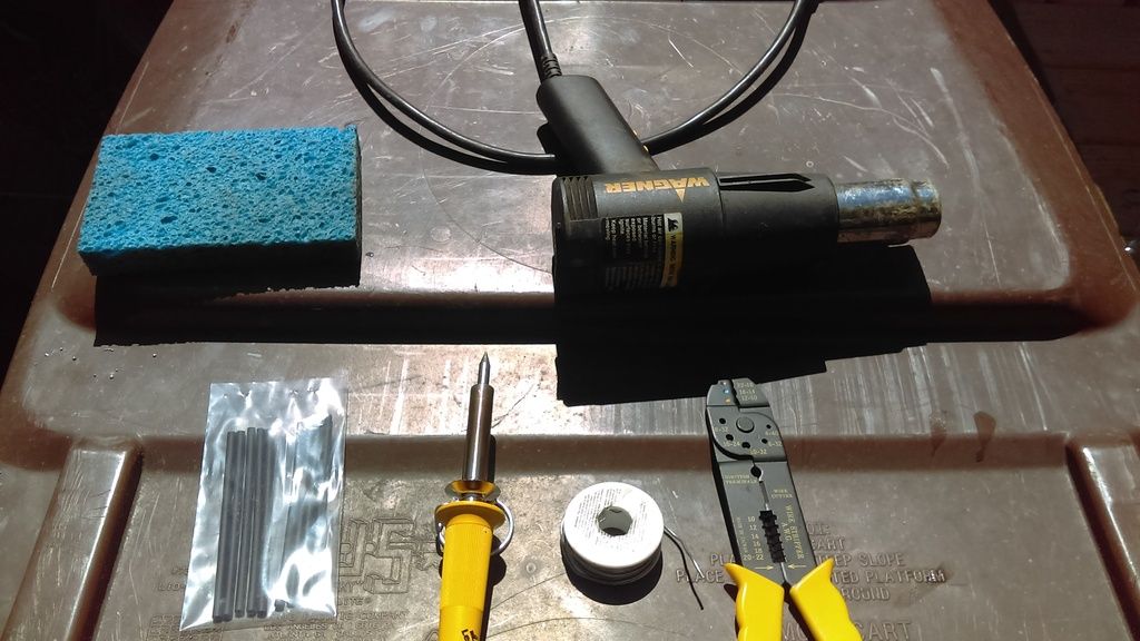
Wire, Wire Cutters/Stripper, Heat Shrink, and Soldering Equipment
I used maybe 2 lengths of 8' of 18 gauge wire. I also have just a basic 40w soldering iron, a spool of electric solder, generic wire cutters/stripper, a damp sponge to clean the soldering iron, and a heat gun to shrink the heat shrink.
A Drill and Drill Bits:
This is to mount the switch in your choice of area.
A Closed Momentary Switch:
Meaning that the circuit operates normal when the switch isn't pressed.
This whole project has taken me about an hour to get everything wired in. Tuning it is a bit easier though.
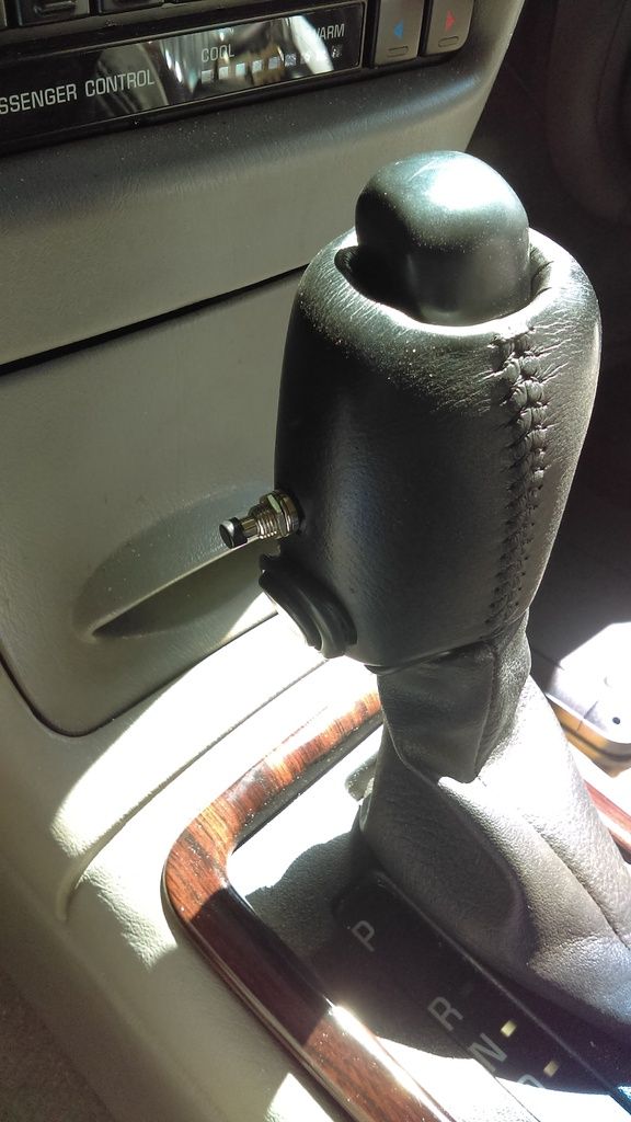
Step 1: Wiring/ Mounting the Switch.
I Started out by drilling a hole in the shift knob, and drilling a hole in the elongated bottom part to run the wires. I would put it in a spot that is easy to reach. I then routed the wires through the bottom of the center console and out of the passenger side port in the fire wall.
Link to the wire routing write up: http://www.clubgp.com/cgi-asp/mods.asp?modid=2
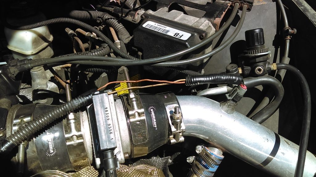
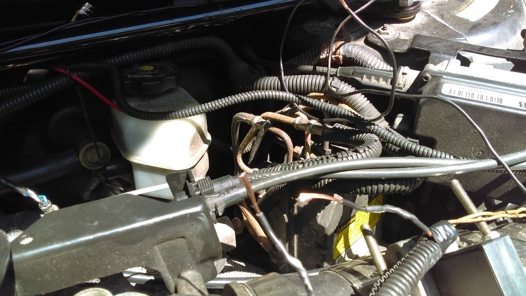
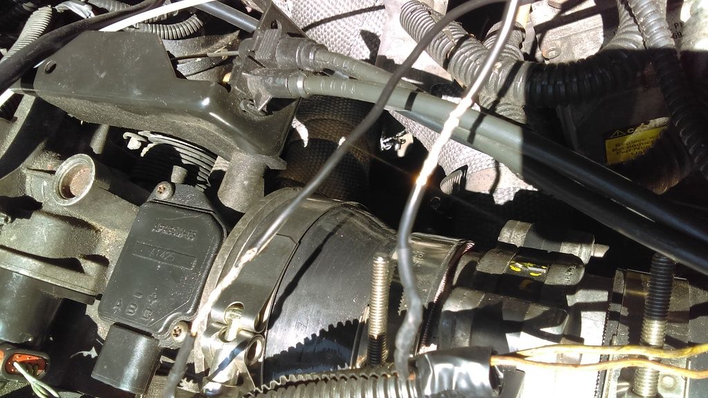
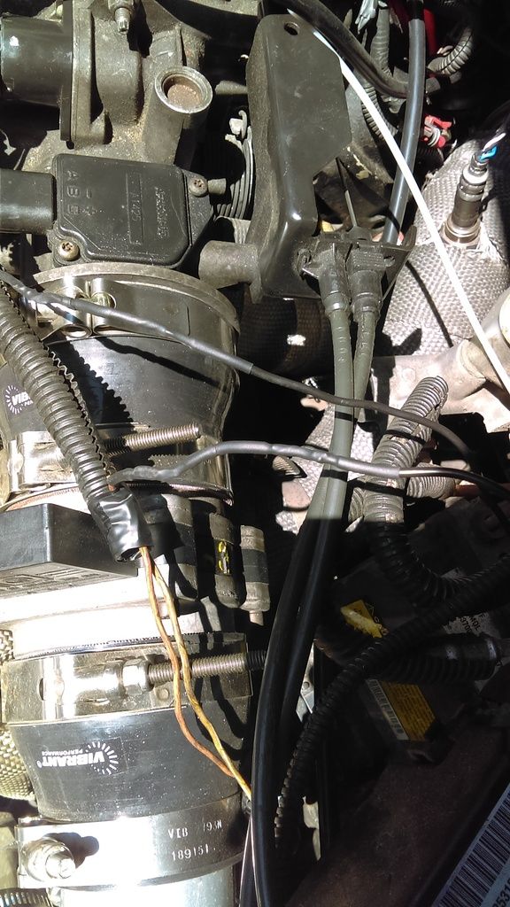
Step 2: Soldering the switch wires to the IAT.
I ran the wire up and around the firewall, being careful to avoid exhaust and spinning/moving parts. I then chose the orange wire to slice in to. It is important that you only splice into one wire, not both. I then cut some heat shrink, put it on the wire. After that i stripped the wires and got them ready to splice.
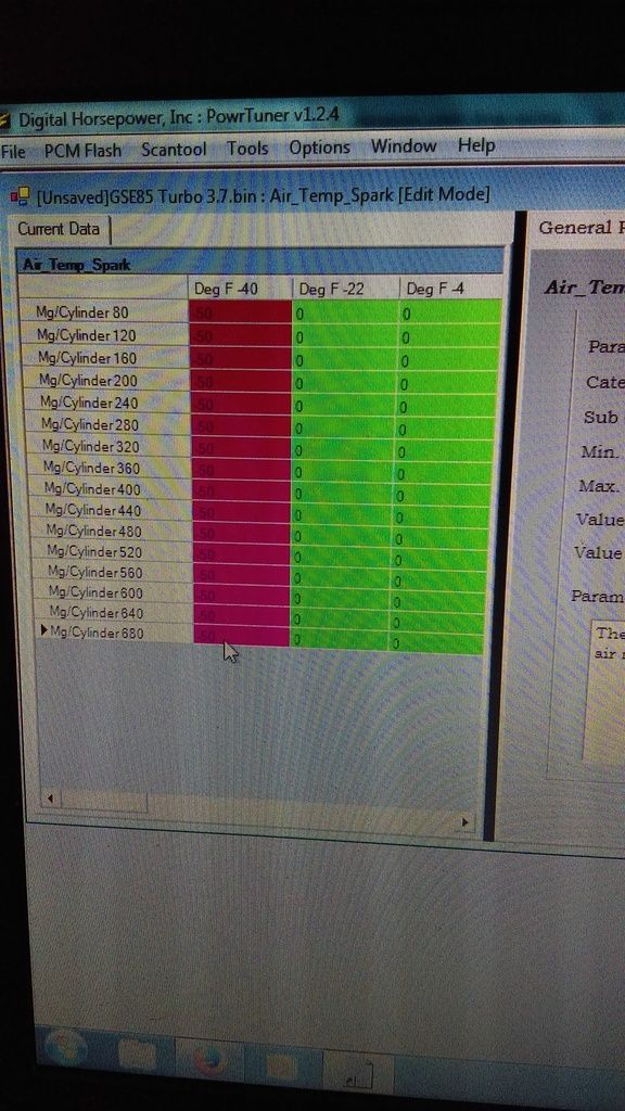
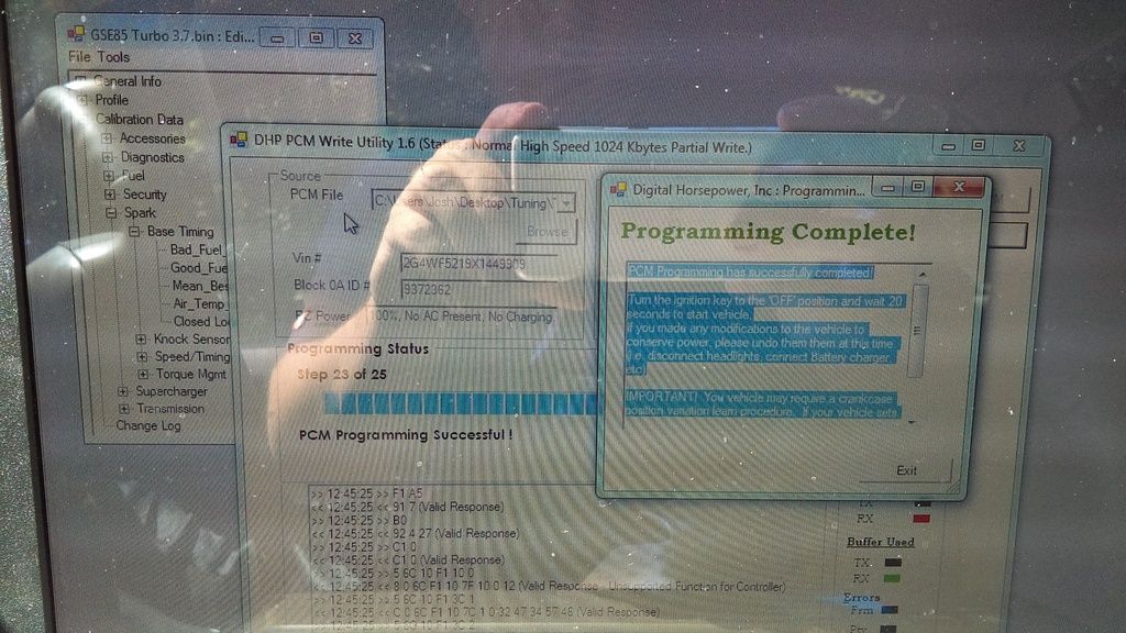
Step 3: Tuning.
Now you go into your bin file and go to Spark>Base Timing>Air Temp Spark. make the full -40 table read -50 and save.
Note: The minimum allowable spark advance does not need to be modded at all.
Here is a video of the IAT Switch in action (with the car off.)
Good Luck. Ill update when i find a number that works on the min spark advance allowed table.
Things You'll Need
DHP or HPT (I used DHP)
Tiny Tuner:
Because you'll have to make some changes that DHP doesn't have options for. Note: No longer needed.
Wire, Wire Cutters/Stripper, Heat Shrink, and Soldering Equipment
I used maybe 2 lengths of 8' of 18 gauge wire. I also have just a basic 40w soldering iron, a spool of electric solder, generic wire cutters/stripper, a damp sponge to clean the soldering iron, and a heat gun to shrink the heat shrink.
A Drill and Drill Bits:
This is to mount the switch in your choice of area.
A Closed Momentary Switch:
Meaning that the circuit operates normal when the switch isn't pressed.
This whole project has taken me about an hour to get everything wired in. Tuning it is a bit easier though.
Step 1: Wiring/ Mounting the Switch.
I Started out by drilling a hole in the shift knob, and drilling a hole in the elongated bottom part to run the wires. I would put it in a spot that is easy to reach. I then routed the wires through the bottom of the center console and out of the passenger side port in the fire wall.
Link to the wire routing write up: http://www.clubgp.com/cgi-asp/mods.asp?modid=2
Step 2: Soldering the switch wires to the IAT.
I ran the wire up and around the firewall, being careful to avoid exhaust and spinning/moving parts. I then chose the orange wire to slice in to. It is important that you only splice into one wire, not both. I then cut some heat shrink, put it on the wire. After that i stripped the wires and got them ready to splice.
Step 3: Tuning.
Now you go into your bin file and go to Spark>Base Timing>Air Temp Spark. make the full -40 table read -50 and save.
Note: The minimum allowable spark advance does not need to be modded at all.
Here is a video of the IAT Switch in action (with the car off.)
Good Luck. Ill update when i find a number that works on the min spark advance allowed table.
Last edited: