95naSTA
New member
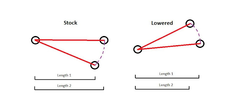
Hello lowered people wanting to improve their ruined geometry and roll center.
I've been slowly working on a custom ball joint solution for my Bonneville which could be done in the same way on a W-body.
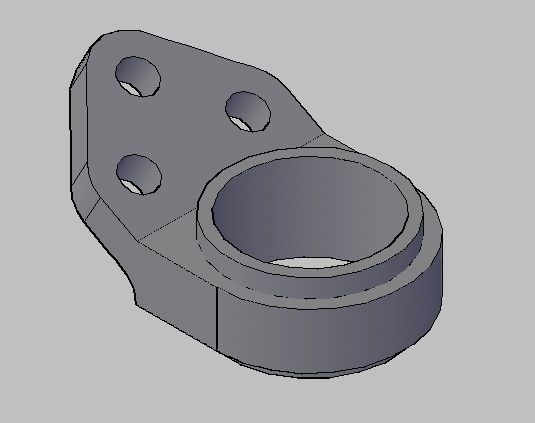
I'm working with a Chrysler 727 screw in style ball joint with adjustable studs from Howe Racing. I modeled a carrier for a threaded sleeve for the ball joint so it bolts to the stock control arm similar to how your W-body's LCAs are.
I originally made a 3d version of the carrier, went hunting for someone to cnc it for me, and no one would.. 2 planes at a weird angle and too much setup time.
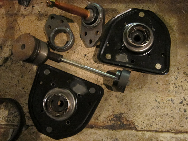
I went to a 2D version considering how my LCAs were just above neutral anyways. I had my knuckles reamed out with a 10* reamer and the tie rod locations flipped via bushings also. When I went to bolt it up the stud did not have the range of motion needed to bolt the strut to the knuckle. It's the angle of the ball joint stud through the knuckle and the large diameter + low range of motion stud that I didn't account for. That angle the ball joint goes through the knuckle is the killer..
After that I was actually able to find someone willing to machine the carrier for me and use a 3D printer to give me a prototype to test. I have that prototype now and a few different length of stud to test out.
The two main problems with something like this is:
1: rotor clearance
2: pushing knuckle in via extended stud and fixed angle of it through the knuckle
The second can be remedied via a longer ball joint carrier, but then it adds to the first.
Ideally I would like to fit all this under a 16x8 x-lace wheel and 12" F-body setup. (that combo already works) So the sweet spot is spacing the ball joint below the rotor but not too far.
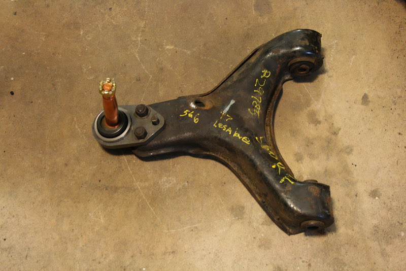
Here's the original:

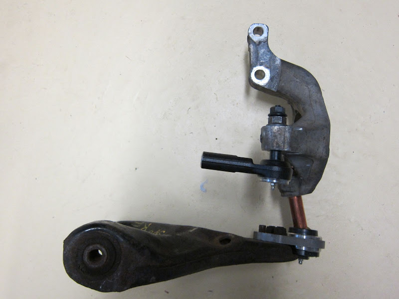
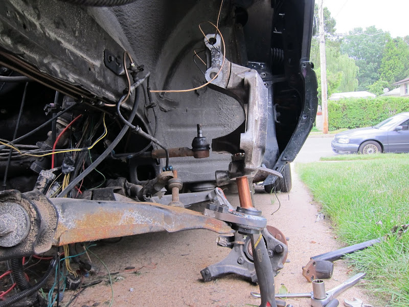
Here's some pics of the progress:


Progress has been and will be slow but I wanted to kick this up on here to maybe motivate others to do similar.
I've been slowly working on a custom ball joint solution for my Bonneville which could be done in the same way on a W-body.
I'm working with a Chrysler 727 screw in style ball joint with adjustable studs from Howe Racing. I modeled a carrier for a threaded sleeve for the ball joint so it bolts to the stock control arm similar to how your W-body's LCAs are.
I originally made a 3d version of the carrier, went hunting for someone to cnc it for me, and no one would.. 2 planes at a weird angle and too much setup time.
I went to a 2D version considering how my LCAs were just above neutral anyways. I had my knuckles reamed out with a 10* reamer and the tie rod locations flipped via bushings also. When I went to bolt it up the stud did not have the range of motion needed to bolt the strut to the knuckle. It's the angle of the ball joint stud through the knuckle and the large diameter + low range of motion stud that I didn't account for. That angle the ball joint goes through the knuckle is the killer..
After that I was actually able to find someone willing to machine the carrier for me and use a 3D printer to give me a prototype to test. I have that prototype now and a few different length of stud to test out.
The two main problems with something like this is:
1: rotor clearance
2: pushing knuckle in via extended stud and fixed angle of it through the knuckle
The second can be remedied via a longer ball joint carrier, but then it adds to the first.
Ideally I would like to fit all this under a 16x8 x-lace wheel and 12" F-body setup. (that combo already works) So the sweet spot is spacing the ball joint below the rotor but not too far.
Here's the original:
Here's some pics of the progress:
Progress has been and will be slow but I wanted to kick this up on here to maybe motivate others to do similar.