• The site migration is complete! Hopefully everything transferred properly from the multiple decades old software we were using before. If you notice any issues please let me know, thanks! Also, I'm still working on things like chatbox, etc so hopefully those will be working in the next week or two.

Devilsown Stage 2 Progressive Alcohol Injection Install...

Iron Indian

New member
Hey Guys,

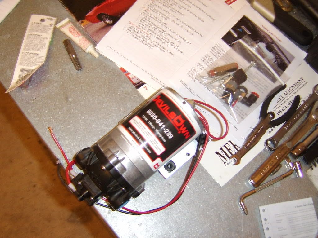
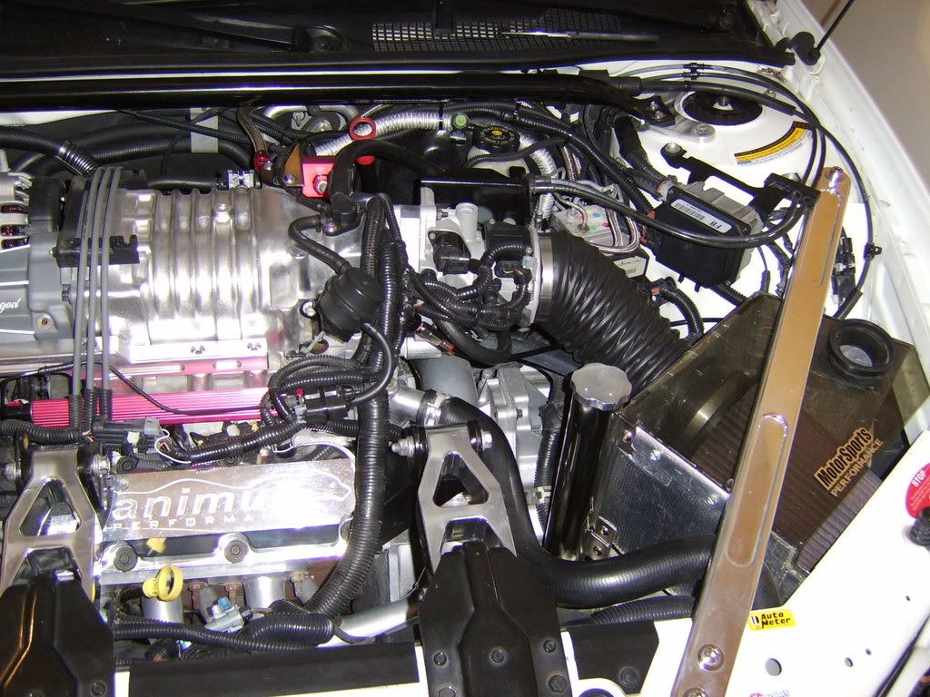
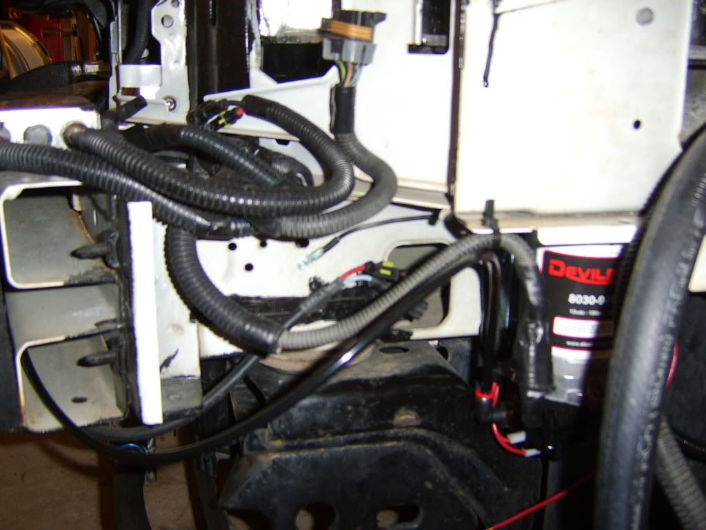
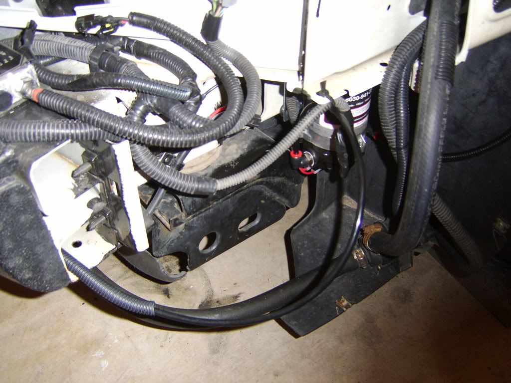
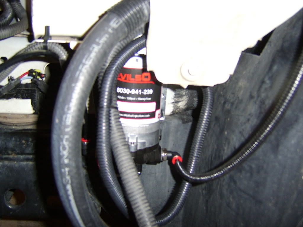
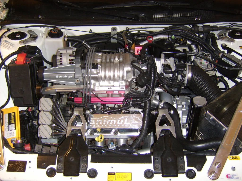
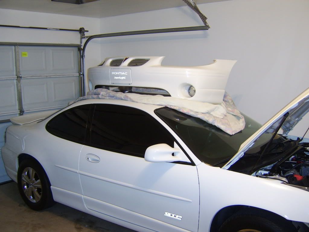
I haven't been on much lately, been working mostly 16 hour days which leaves me pretty much worn out. I had a little bit of time on Saturday and Sunday to get my Devilsown Stage 2 Progressive 3800 Alky Kit installed on my 1999 GTP. Here are my pics...


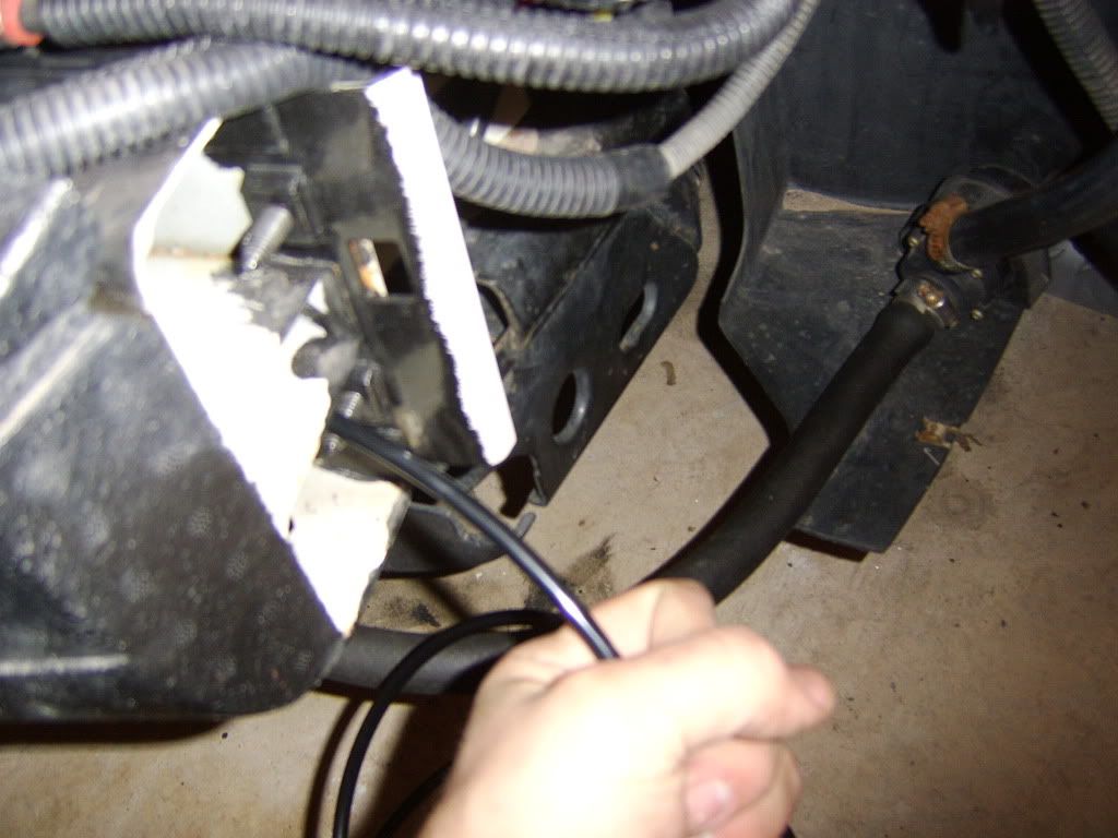
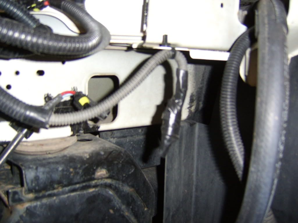
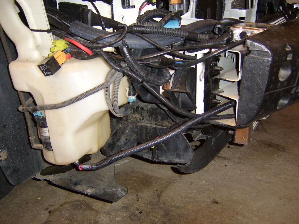
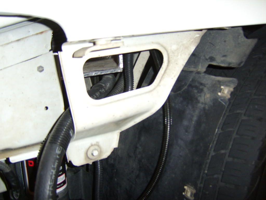
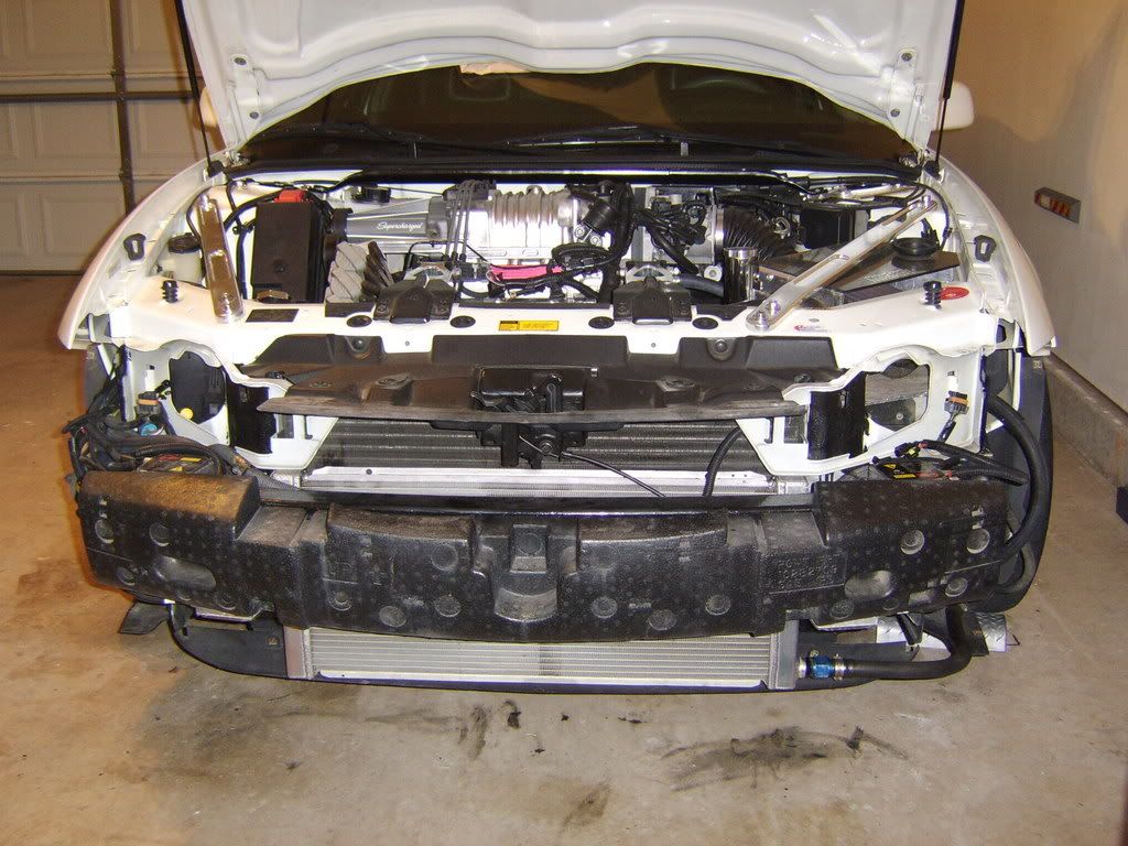
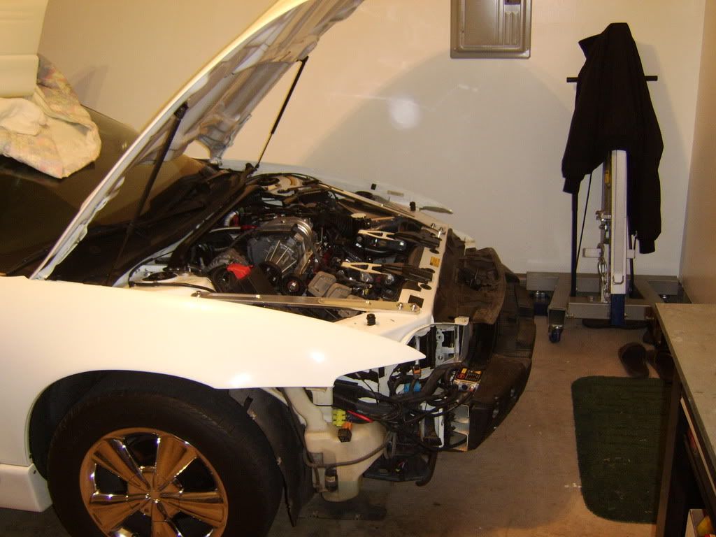
Bumper removed ready to get started...

Picture026.jpg


Picture028.jpg


Picture027.jpg


Picture029.jpg


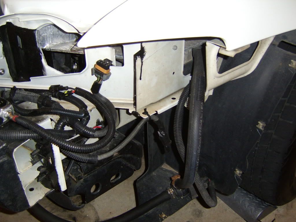
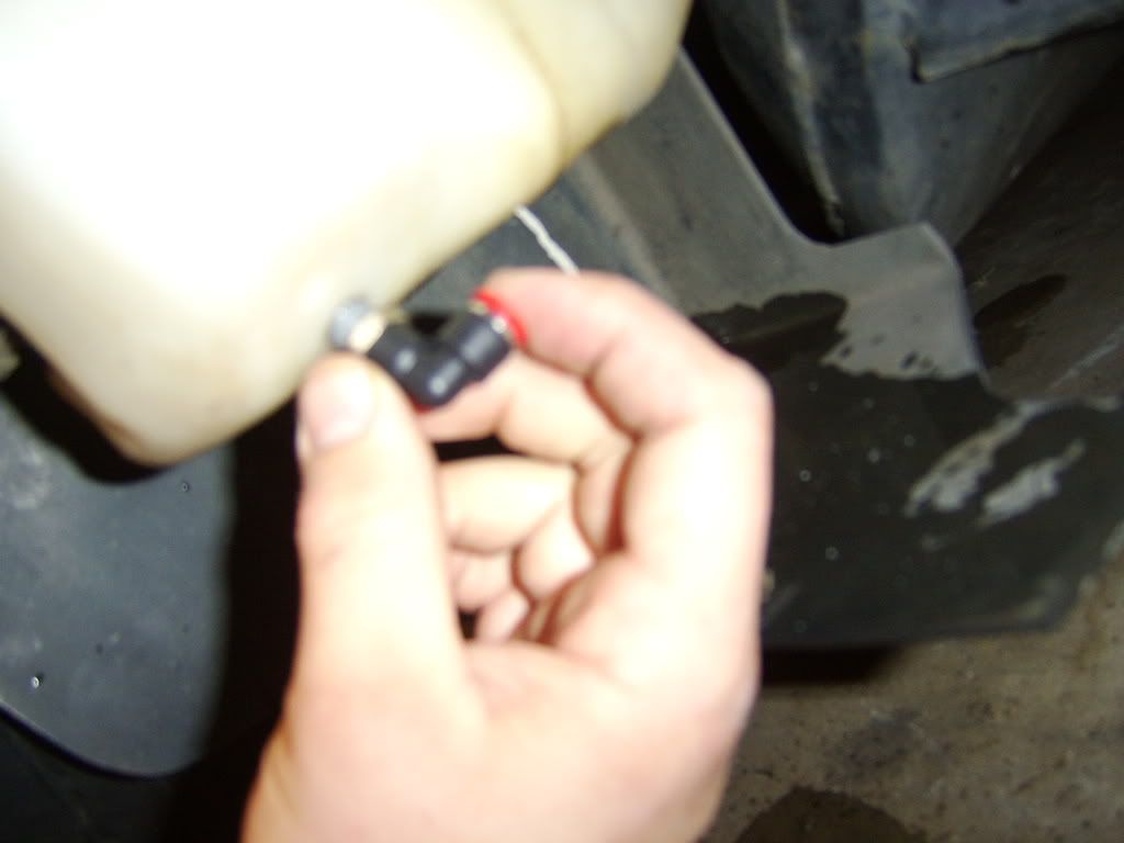
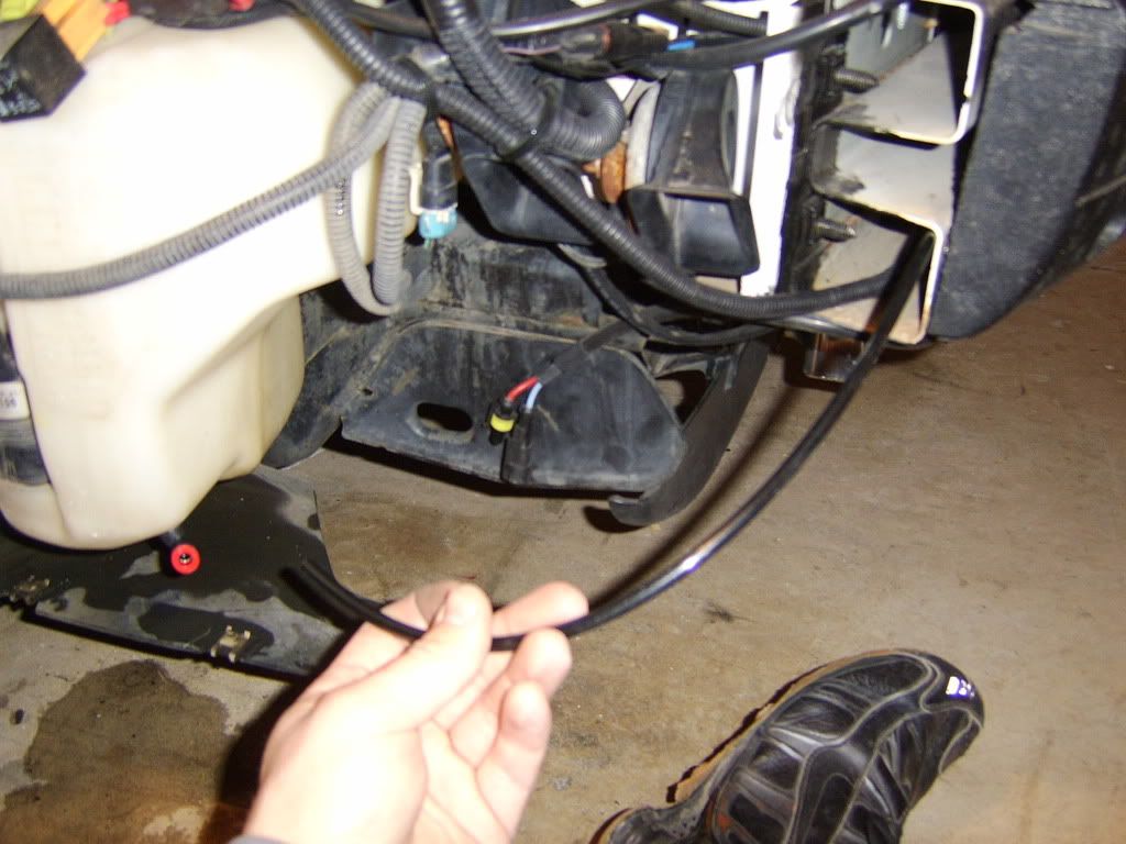
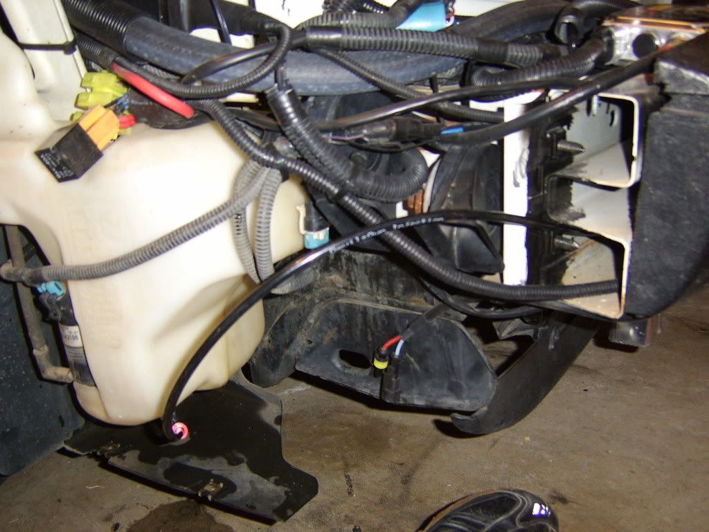
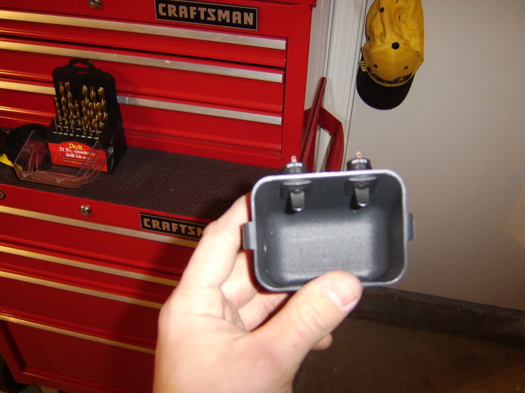
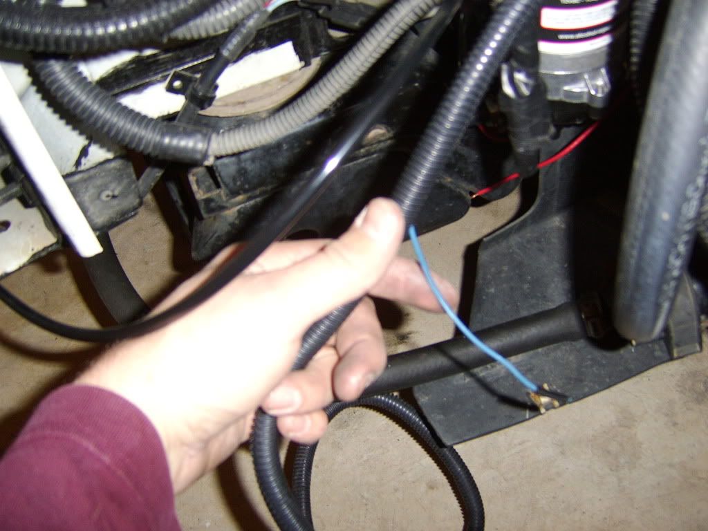
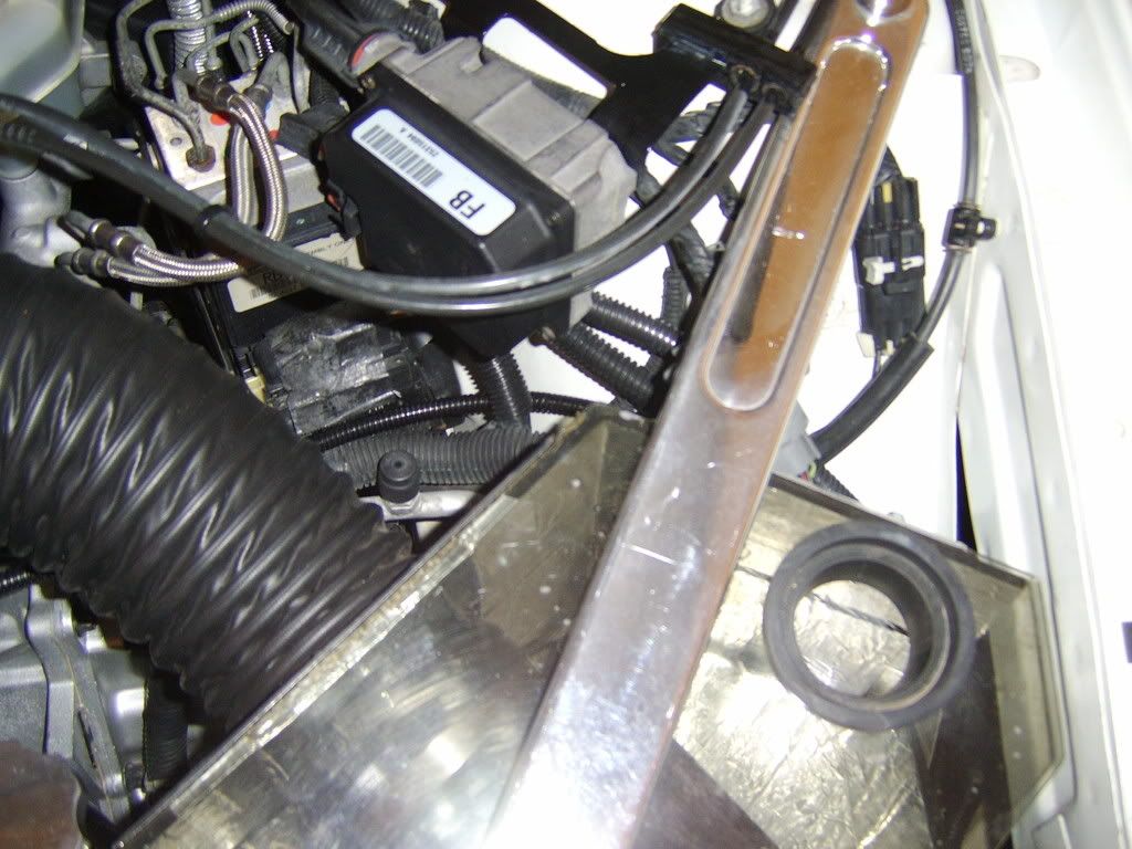
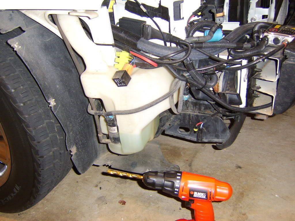
Theres my washer tank, time for some modifications...

Picture030.jpg


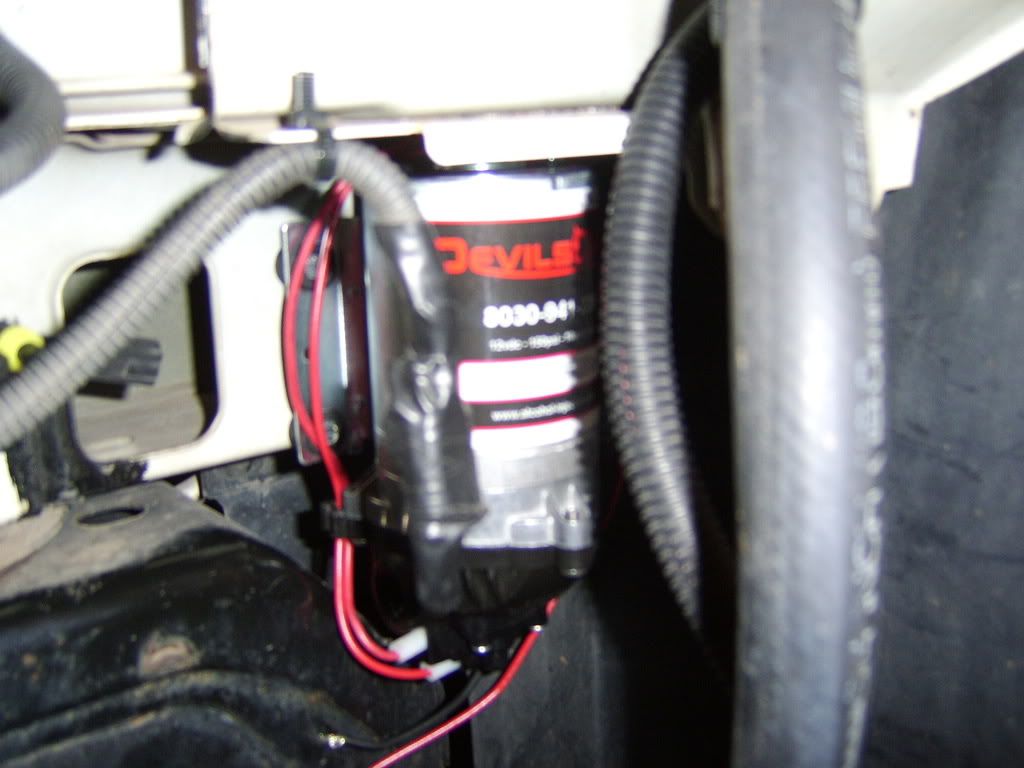
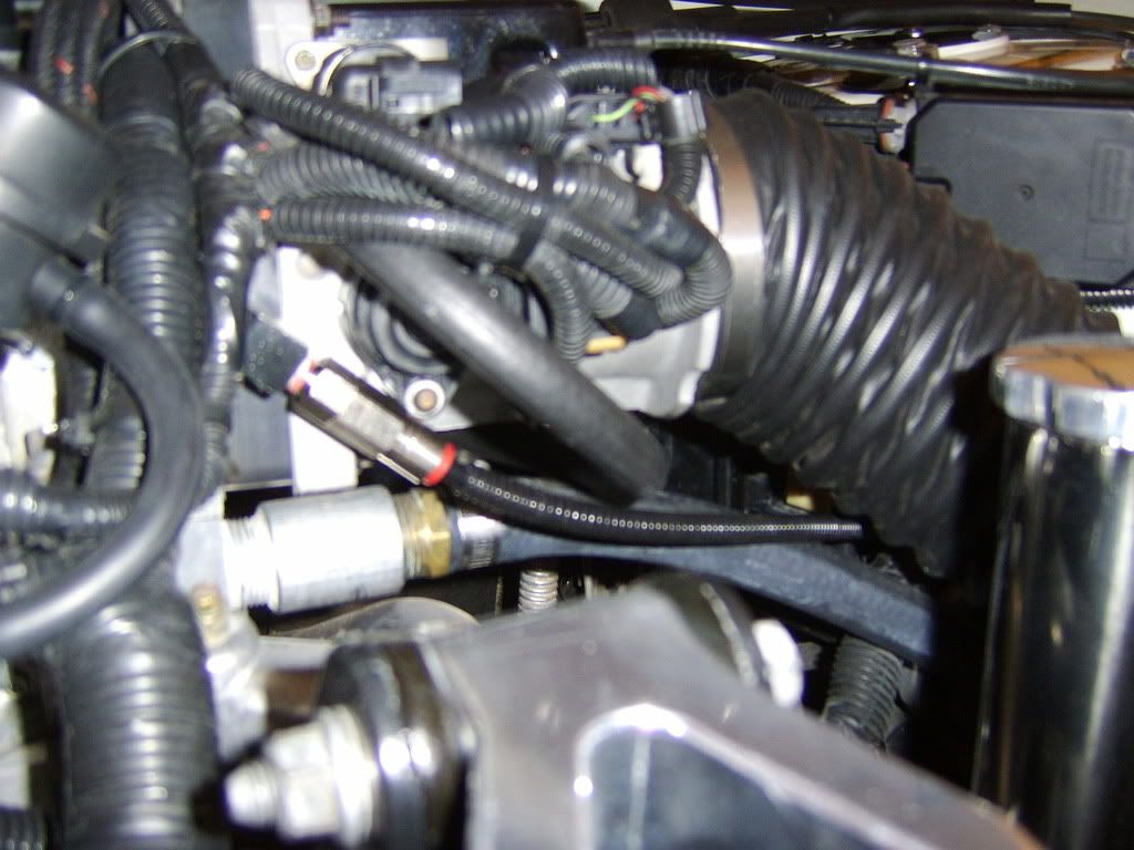
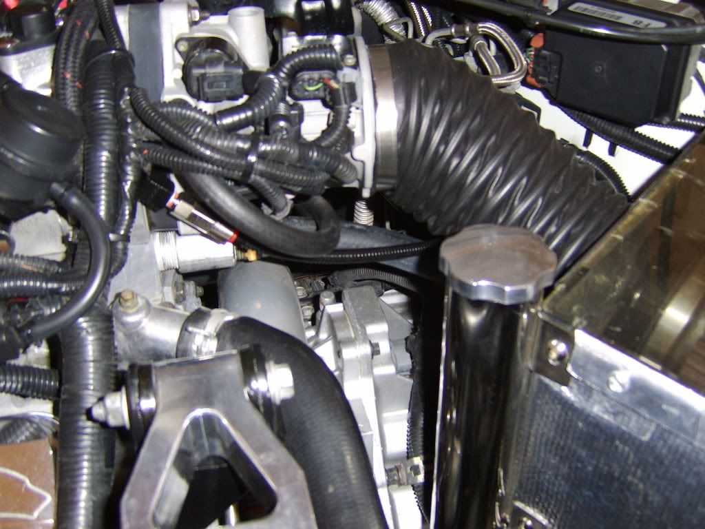
Nice flat indention, perfect for a fitting...

Picture031.jpg


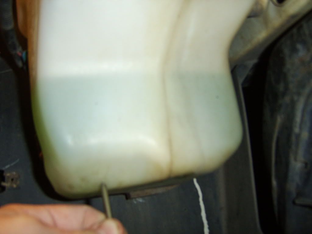
Scoring a mark/bit guide...

Picture032.jpg


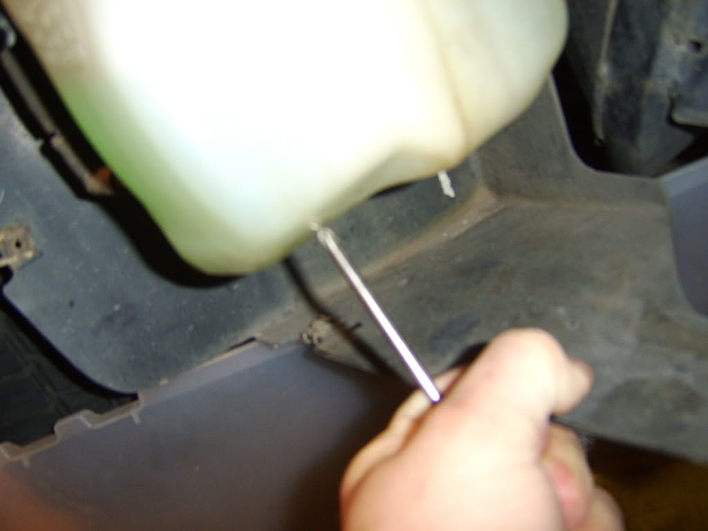
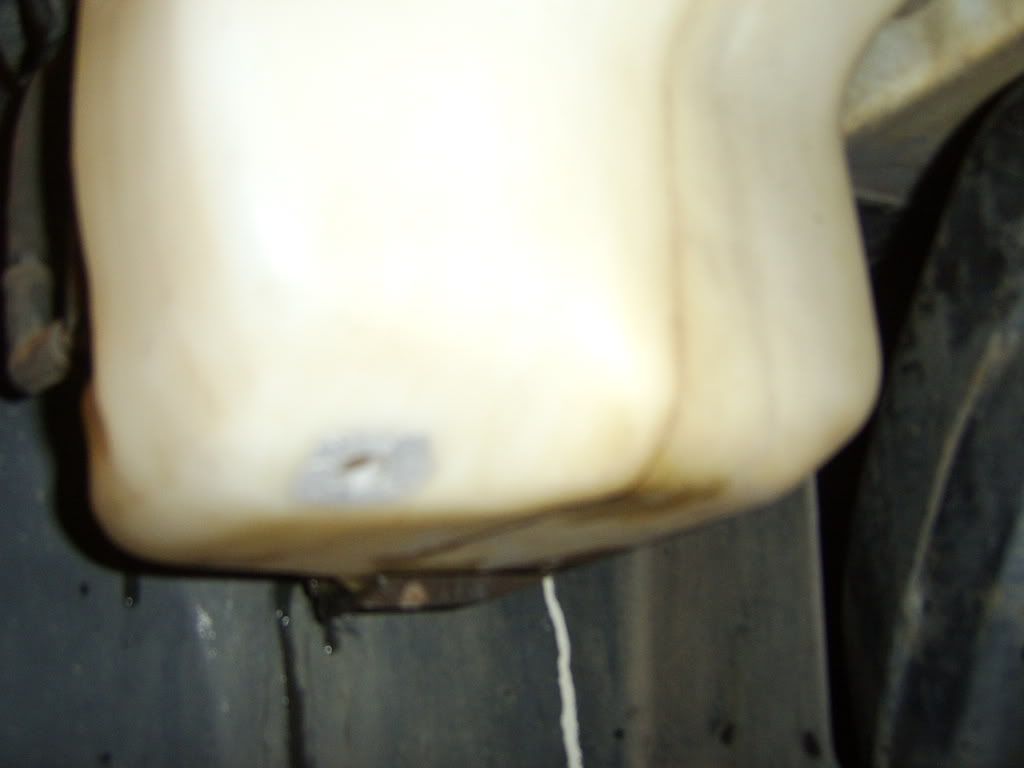
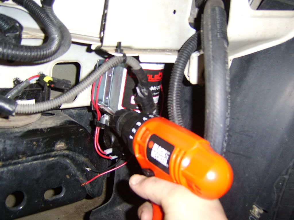
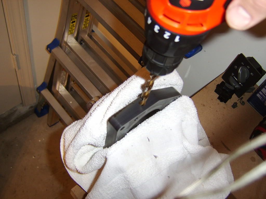
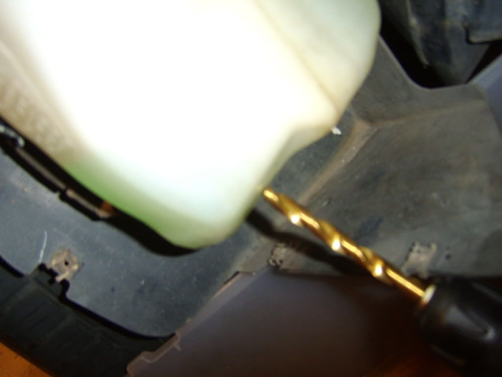
Drilling the hole...

Picture033.jpg


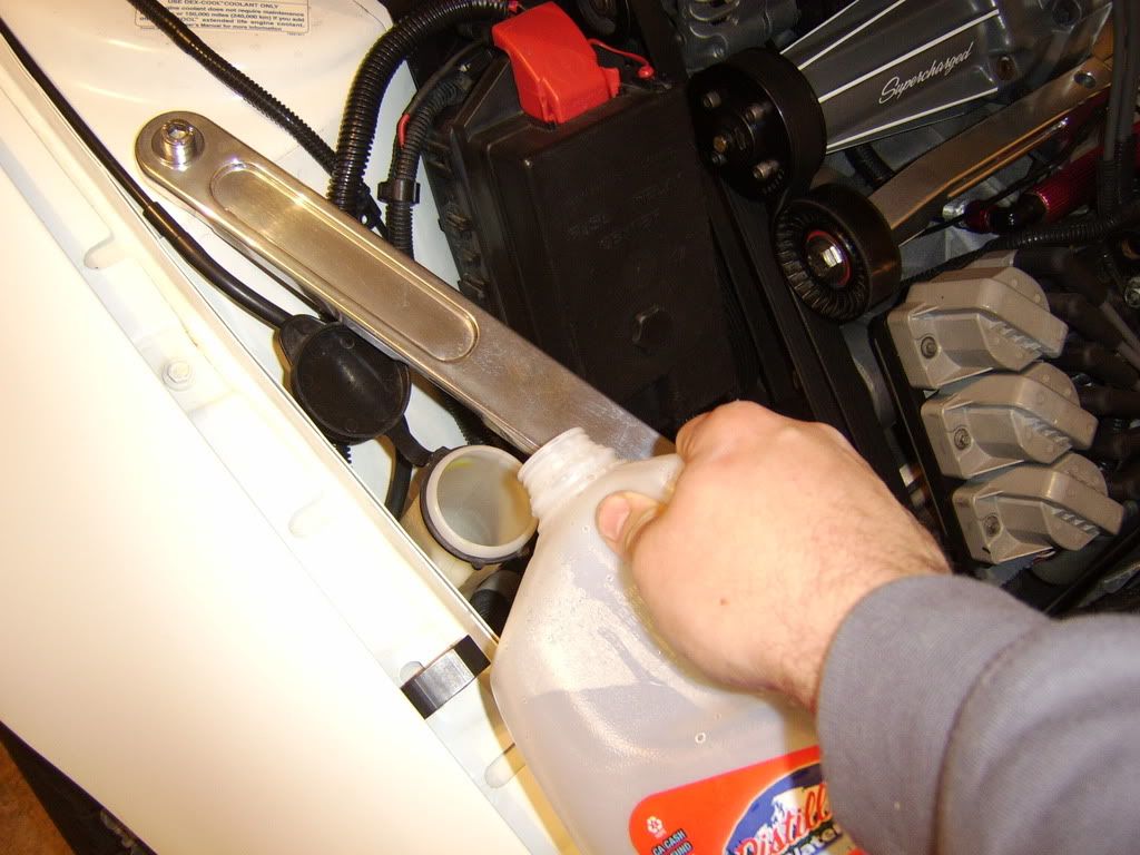
Flushing out the shavings with distilled water...

Picture034.jpg


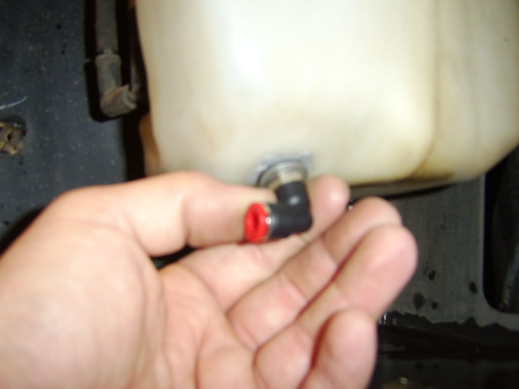
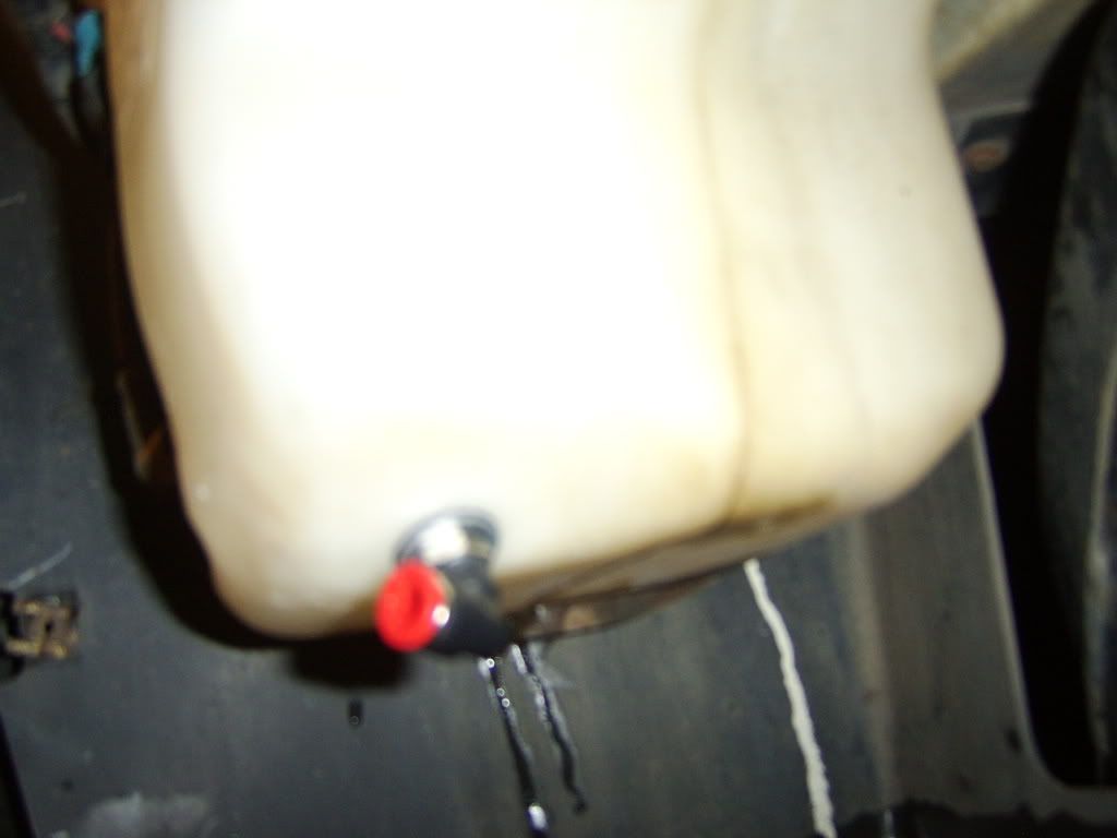
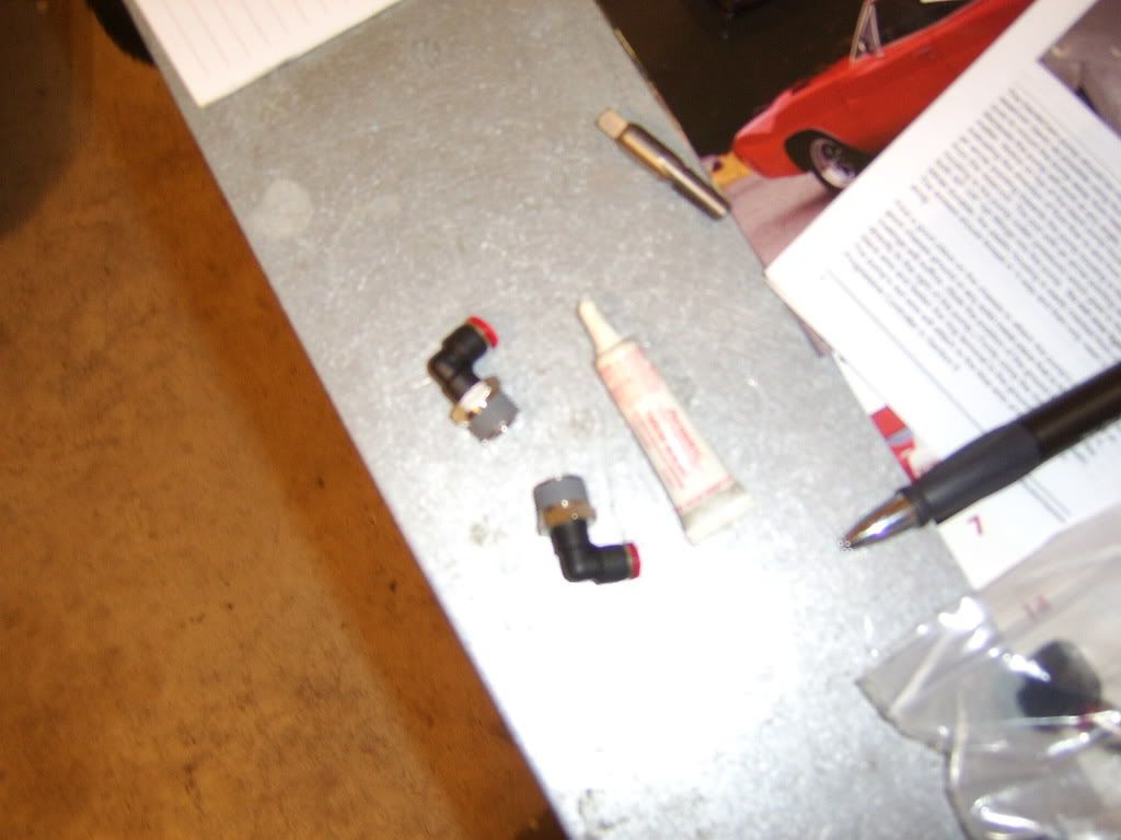
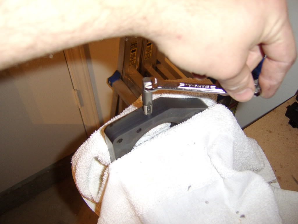
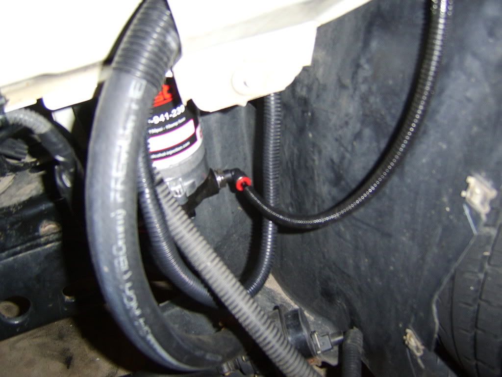
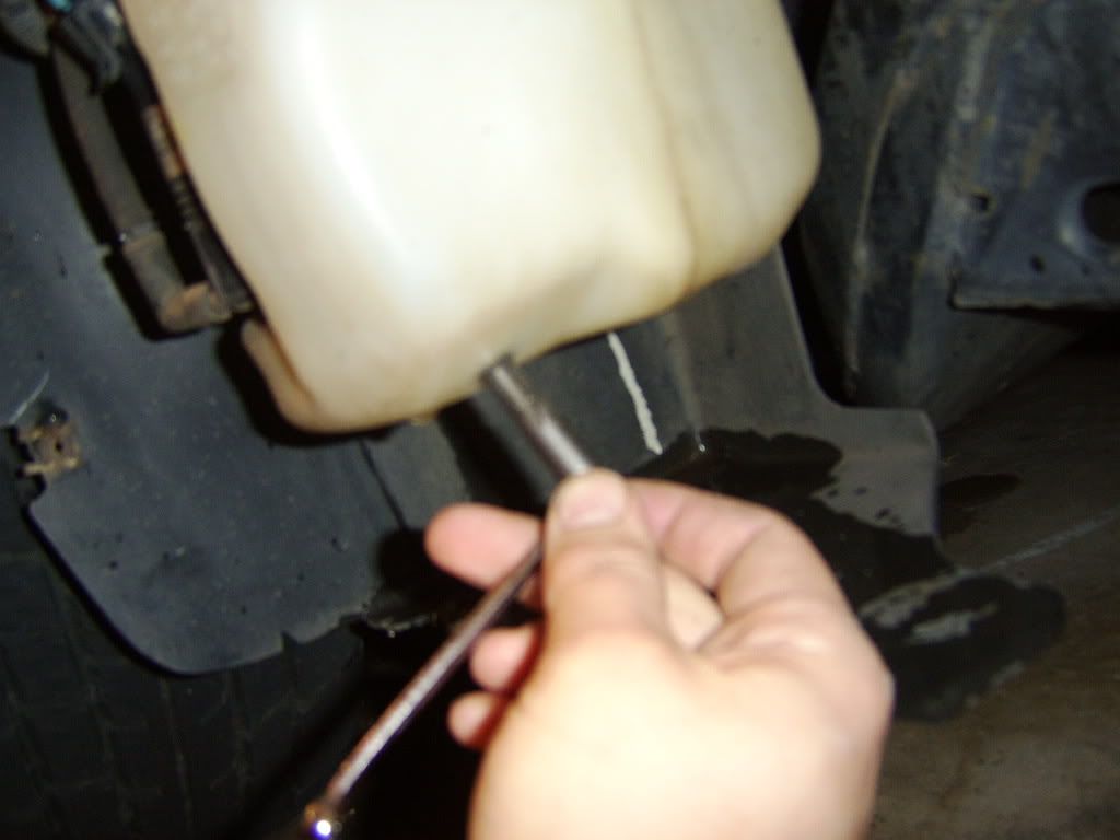
Tapping threads into the tank using an 1/8"-27 NPT tap...

Picture035.jpg
 
Last edited by a moderator:


Re: hkjljlkkln

Flushing out the shavings once more...

Picture034.jpg


Testing the new threads I made...

Picture036.jpg


Fitting and washer with rubber seal I'll be installing...

Picture037.jpg


Fittings with some thread sealer and grey RTV which will be used...

Picture038.jpg


Fitting, washer, rubber seal put together and thread sealer applied...

Picture039.jpg


A little RTV applied on the washer tank itself, overkill I know, but way not use it too?

Picture040.jpg


Installing prepped fitting...

Picture041.jpg


Fitting tightened and ready to go! Note, Elbow swivels too.

Picture042.jpg


Now its time to run some tubing...

Picture044.jpg


Starting from the drivers side, i'm running the tubing through the bumper support, going to the passenger side...

Picture045.jpg
 
Re: hkjljlkkln

There it is...

Picture046.jpg


Connected to the washer tank! Be sure to leave plenty of excess tubing, keep in mind, you have some fog light buckets to clear once the cover is back on...

Picture047.jpg


Now its time to mount the pump and run the tubing to and from it...

Picture048.jpg


Here's where I plan to mount it, score some marks and drill some pilot holes. The kit comes with self tapping sheet metal screws, but I always prefer drilling a pilot to make the screw go in easier. Its up to you...

Picture050.jpg


Installing the pump to its new home...

Picture051.jpg


Mounted and ready to roll...

Picture052.jpg


Fittings for the pump, I used a little bit of thread sealer before installing. BECAREFUL TO NOT OVERTIGHTEN THE

FITTINGS INTO THE PUMP, THE BODY IS PLASTIC!!! Note, Elbow swivels too.

Picture053.jpg


Fittings installed and ready to go, i'll wire it up later...

Picture054.jpg


Heres my prerun tubing, time to run it to the pump, make sure to pay attention to which way the flow arrows are

marked on the pump. Be sure to leave excess tubing when mounting the inlet tube.

Picture055.jpg


Picture056.jpg
 
Re: hkjljlkkln

Picture057.jpg


Time to run some tubing out of the fenderwell and into the engine bay...

Picture058.jpg


Picture059.jpg

Now its time to tap a nozzle into the motor. Luckily for me, I already have a TB spacer perfect for this job.

Bewarned, with my setup it was quite difficult to figure out a GOOD place to mount the nozzle. It took me quite

awhile looking at it to figure out my best route away from heat and moving linkages...

Picture060.jpg


TB spacer off the car and on the work bench...

Picture061.jpg


Time for some drilling...

Picture062.jpg


Then my handy 1/8"-27 NPT Tap...

Picture063.jpg


Mocked up DO5 nozzle and 90 degree elbow...

Picture064.jpg


Picture065.jpg


Picture066.jpg
 
Re: hkjljlkkln

After several test fits on the S/C with the TB in place I found the perfect angle to mount the nozzle, elbow, and

check valve. I used thread sealer on all the connections, just to be on the safe side. It certainly doesn't hurt a

thing. It enters right below the TPS sensor, you'll see...

Picture067.jpg


Picture068.jpg


Picture069.jpg


Picture070.jpg


Picture071.jpg


Picture072.jpg


Picture074.jpg


Picture075.jpg


TB spacer and TB reinstalled with gasket matched OEM Gaskets with a little bit of Grey RTV to help sealing.

Picture003.jpg


Picture002.jpg
 
Re: hkjljlkkln

Now its time to figure out where to place the main control unit for the Devilsown kit. My plan from the begining

was to mount it in the mini cubby by the headlight switch. I already have a couple of switches mounted, why not a

control unit too? It should fit perfect. Here it is removed before modification...

Picture009.jpg


Drilled a hole in the cubby so the control units' wiring can run through...

Picture010.jpg


Mocking up the control unit in its new home...

Picture011.jpg


Picture012.jpg


Now its time for some wiring, first we'll start running the wires, control unit, and modified cubby in to the dash

of the car...

Picture014.jpg


After running it under the dash and nicely looming and seprating wires, I wired in the supplied 10 AMP fuse holder

on the red wire power side and I tapped it into a switched 12V source. Since my Acc Power Drop is pretty much used

up and on the other side of the dash, I used my Autometer Volts gauge power wire as a tapping point and spliced

there. I took the black ground wire crimped on a ring terminal and used an existing bolt for the steering column

mount. I proceeded to run the blue and green wires (longest wires in the bundle) to the passenger side wire

gromment and ran the out into the engine like i've done many times before. After successfully getting the wires

into the engine bay, I loomed them up and started routing the wires to there new homes. The Green wire goes to the

MAP sensor and taps into the middle green wire (B) on the connector. The blue wire goes directly to the pump and

wires into the Red power wire. Posi tap was used for the MAP signal wire connection, a butt connector with heat

shrink was used on on the blue/red pump connection. For the pumps' ground I used a ring terminal and some shrink

wrap to seal it off. Drilled a small hole and shot in a sheet metal screw on the frame rail beside the pump.

Picture015.jpg


Picture016.jpg


Picture024.jpg


Picture023.jpg


Picture025.jpg


Re: hkjljlkkln

038.jpg


036.jpg


035.jpg


Added loom to areas that may rub or get effected years down the road. I love loom, can't live without it! I loom

damn near everything. Devilsown Alky kit completely installed and ready to roll...

026.jpg


027.jpg


028.jpg


029.jpg


030.jpg


031.jpg


032.jpg
 
Re: hkjljlkkln

034.jpg


All I got left to do is reassemble the front bumper/headlights, reinstall my STB, fill the system with fluid (once I figure out/decide what to run), gap my plugs down to .045, and figure out how to tune it. With my work schedule, that won't most likely happen until this coming weekend though. So it looks like the Trailblazer will be my driver this week.

Hopefully my crappy pictures (yeah I know, i'm not a camera man) and brief descriptions help someone out who want to go this route on there GP. Took alot of time and work to get it all on this forum. Hope you guys enjoy this thread...


Wanna sell me that scan master Shawn? How much did ya pick it up for or did ya buy it new?
 
so youre running completely electrical from the MAP and MAF? i havent really looked at my stuff that much since it's cold as hell and i dont want to work in the cold, but i thought there was a port for a vacuum source too? would that not be easier than running off the MAP?
 
so youre running completely electrical from the MAP and MAF? i havent really looked at my stuff that much since it's cold as hell and i dont want to work in the cold, but i thought there was a port for a vacuum source too? would that not be easier than running off the MAP?

i dont follow what you meant by that? i thought the controller only gets tapped into the MAP? does the new kit also reads and tap into the MAF as well?
 
im not sure. i havent looked at it in a while since i havent really been trying to install it in the cold. i know there is an electrical connection to the MAP, but is there anything else? i thought there was a vacuum line as well? maybe a MAF connection too?


o ok, so u werent certain. i have the controller and theres only 3 wires: ground, switched 12v and the wire thats tapped to the map sensor, thats it.

edit-other competitors like snow performance, IIRC, use the MAF sensor as a base of how much to spray the flow, but they're very pricey
 
Good work Shawn! The install is pretty straight forward, and it's fairly easy if you take your time. The biggest PITA for me was wiring the controller, and making it go through it's diagnostic mode so that I could get it to work.
 
Thanks for the compliments guys! I appreciate it!

The Devilsown kit I have uses the MAP only as reference for the Alky system, nothing else. Otherwise its pretty much self contained. I touched on the wiring subject above, Here it is...

After running it under the dash and nicely looming and seprating wires, I wired in the supplied 10 AMP fuse holder on the red wire power side and I tapped it into a switched 12V source. Since my Acc Power Drop is pretty much used up and on the other side of the dash, I used my Autometer Volts gauge power wire as a tapping point and spliced there. I took the black ground wire crimped on a ring terminal and used an existing bolt for the steering column mount. I proceeded to run the blue and green wires (longest wires in the bundle) to the passenger side wire gromment and ran the out into the engine like i've done many times before. After successfully getting the wires into the engine bay, I loomed them up and started routing the wires to there new homes. The Green wire goes to the MAP sensor and taps into the middle green wire (B) on the connector. The blue wire goes directly to the pump and wires into the Red power wire. Posi tap was used for the MAP signal wire connection, a butt connector with heat shrink was used on on the blue/red pump connection. For the pumps' ground I used a ring terminal and some shrink wrap to seal it off. Drilled a small hole and shot in a sheet metal screw on the frame rail beside the pump.

Thats all the wiring needed. No vacuum lines are used either, its all electric.
 
Reptile,

Can you tell me more about this diagnostic mode thing? I don't think I read anything about this in the instruction manual, but its been several days since I looked at it too so I maybe way off. What do I need to basically do? Tips or tricks? Thanks!
 
Back
Top