First off I did not write this guide, and take no credit for such things. It is from ClubGP.com, but since I could not find it anywhere on this site, and found it very useful, I figured it deserved a post here.
username 'Therealkoop' from ClubGP.com says,
"Diy head porting.
Introduction:
My name is Matt Koopikka. I haven’t been a member on this forum for long, but it has provided me with a very large amount of help and information over the time I’ve been here. Now as I demod and move on to new things, I figured I’d try to give back a little. If my credentials are important to you, I will say I’ve taken many high performance automotive classes, as well as 120+ hours of class on top end porting/fueling/airflow. I actually wrote this for a class some time ago, and just adapted it into a guide that this forum could use.
Every few days I see a question or a post on ported heads, superchargers, or just porting in general. Porting itself is not very difficult, it is more a matter of being careful, knowing what to do, using the right tools, and taking your time. Lots, and lots of time. I’m not going to get incredibly detailed, and this will be a very -basic- port and polish job that most should be able to tackle, but you will be surprised at the end results.
Basics:
First off, I suggest you read the standard abrasives porting guide. It covers the basics such as bowls/radii pretty well, and is a good read. The only problem with it is that it’s not specific to the 3800, and that’s what I’m planning on helping with here.
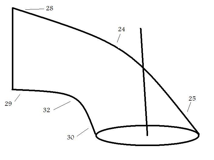
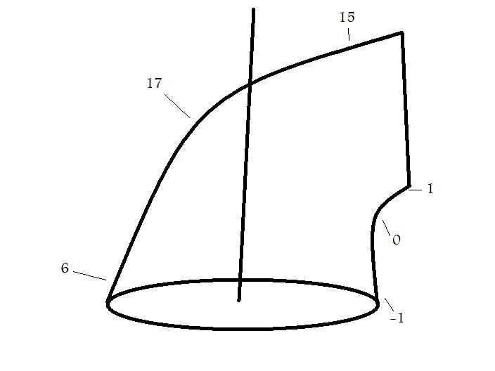
Stock 3800 heads are cast iron, which means they are pretty easy to tear into and start making improvements. Flaws in the heads from mass production can be fixed and with good results with very minimal amounts of work. Something that may be helpful in your understanding of a 3800 head is how air flows though its ports. I’ve made these simple diagrams that illustrate flow, since I believe if you know how things are working, it’s easier to work with them, and if you wanted to take you’re porting to a level that this guide won’t go into, and then you may have a chance of making intelligent decisions. These readings were done on a flow bench with the proper tools, and at the standard of 28in/h2o. As air is flowing through the port, you use a tool to measure flow across the port. This helps with the design of your port. All measurements are done in in/hg.
Intake: As you can see from the diagram, air flows pretty evenly across the entire port, with a small emphasis on the bottom of the port, but maintaining decent velocity. I will also note that raising the floor or lowering the “roof” (making the port smaller to increase velocity) of the port will result in -significant- decreases in flow, with no real benefit to velocity.
Exhaust: Much more apparent in this diagram then the intake, you can see that air has a very distinct path when flowing through the exhaust port. Almost all of the air will flow across the top of the port, meaning that raising the roof of the port could increase flow, and lowering the bottom is probably not beneficial.
Preparation:
Before we start were going to need tools. Everything I do in this guide will be done using one tool and one tool only. An air powered die grinder. I will only use two tips for simplicity, and those are a basic ¼” drum shank, and 80 grit paper roll cartridges. You can do this with a dremel and stone tips, but by the end of a pair of heads, you will probably burn up at least one dremel tool and many, many tips. Obviously, I do not suggest going this route.
Before you start grinding away make sure you are in a good area to do so. There will be a horribly ridiculous amount of metal filings and shavings all over and around your workplace, so you might not want to do this in your living room. Also make sure you are in a well lighted area. A shop light or adjustable light will help immensely, and it is hard to see down into the port (and what you are porting/potentially damaging) without one. I also suggest wearing some safety goggles, as annoying as they are. A radio is nice too.
Make sure you have enough room to lay your heads out and be comfortable, you are going to be here for a while if you want to get anything done. I like to have a table long enough to set my heads up in a straight line. This is for a very important reason, so you can do ONE small modification to EVERY port on each head in a row. I do not suggest fully porting a single port, then moving to the next one. This will lead to uneven flow/design in different ports, and is just a bad idea. If you do this you will probably find that the first port you make is much better than your final one, because you’ll just want to be done by the time you hit your sixth exhaust port and just cut corners. Even if you were devout and didn’t cut corners, it would be quite difficult to make symmetrical ports in this way.
Now that were all setup, let’s get to business…
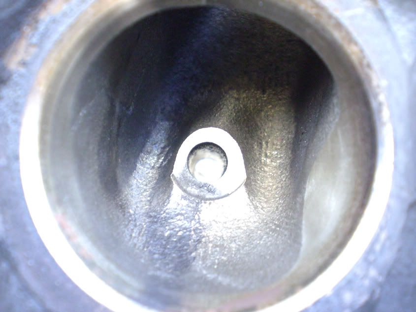
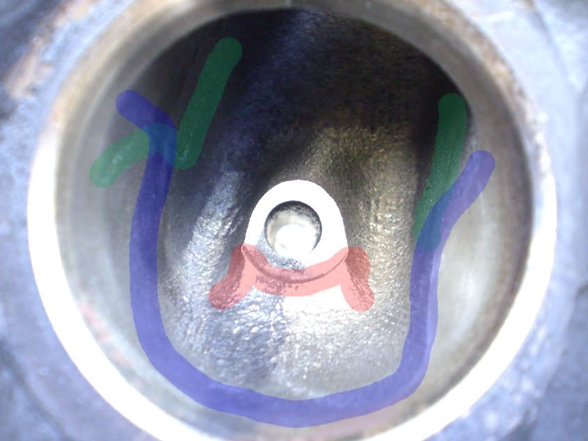
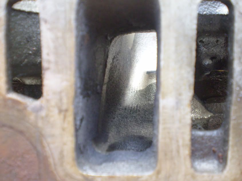
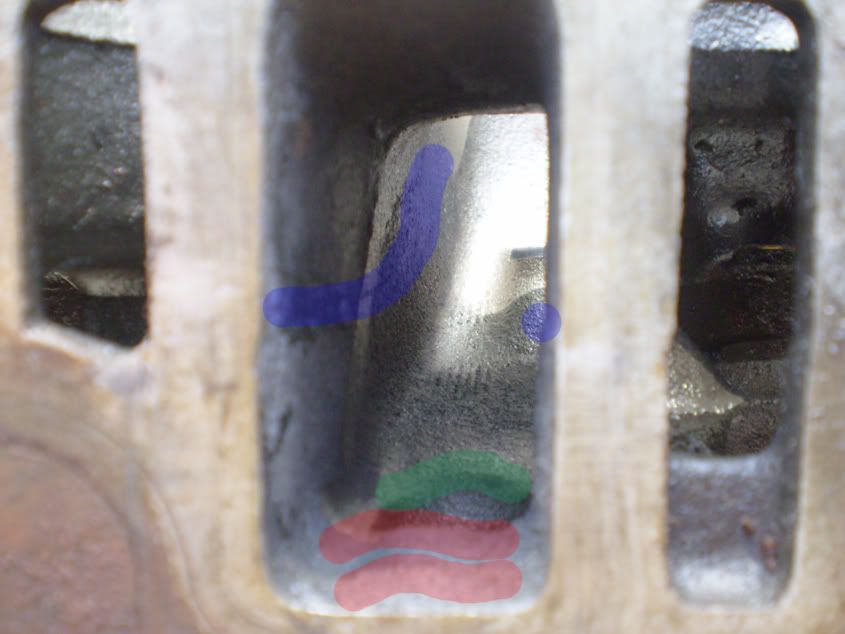
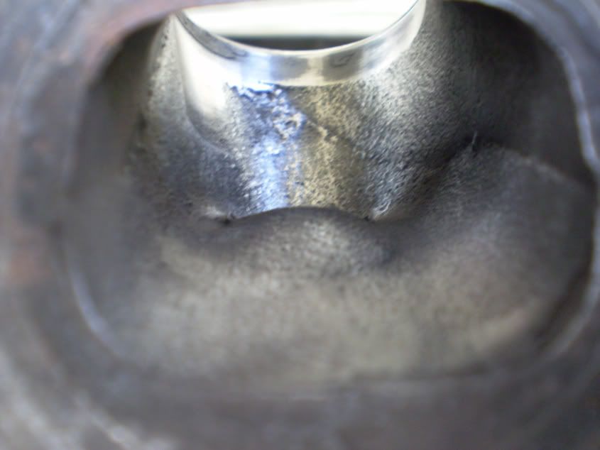
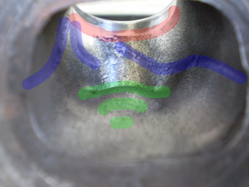
I’ve highlighted some more important parts on this intake bowl. Obviously, you are going to want to start by removing all the porous casting marks that are inside of the entire port, as well as any carbon deposit. This along with the short side radii are arguably the most important part of flow in any head, be it production or aftermarket aluminum. When porting, use your fingers to feel around for imperfections and to test your work.
The green highlights a very large and hindering casting mark that runs down either side of the port, it’s easy enough to remove without much caution. Jut casually blend this in with your tool to make it perfectly smooth with the rest of the port.
The blue is another large casting mark that follows the inside of the bowl and features two large humps that effectively make a small bottleneck right above the valve head. This one you have to show a bit more caution on, since it is very close to the valve seat. Go slow and take your time. After you have removed the “line” from casting, go ahead and remove the “lumps” that they follow on the left and right of the valve guide, right above the valve seat
The red highlights the valve guide. There is a restrictive lip on the outside of the guide that can be removed safely. DO NOT remove material from the actual guide that would touch the valve. Be careful here as well, if you were to nick the inside of the valve guide it could cause problems later on. In the third picture, the red highlights a sharp ridge on the short side radii. There is proof that this ridge is a good thing, and it actually increases flow. The only thing I really suggest doing with the short side radii is smoothing out the casting marks. Do not grind out material, or remove this ridge. You can take the edge off of it if you want, but leave its basic shape intact.
Now let’s take a look at the intake runners:
Like before, remove all the porous casting marks all along the inside of the port. I’ve again highlighted areas of interest inside of the port.
The Green in this picture is a small ridge that was made when drilling the holes for the injector bosses. This can be smoothed out to a nice gentle curve. You don’t have to worry about the injector seating incorrectly, because the injector is placed on the outside of the head.
The blue in this picture is the other end of the casting mark from the bowl side we saw earlier. As you can see it really does go all the way through the port. Smooth this out like you did before. Be careful not to mar up the intake gasket surfaces.
The red is a lump from the injector area once again. Some may say this creates a low pressure area over the injector that helps atomize fuel, but I wasn’t worried about it and removed it anyway to make it flush with the rest of the port.
Ill also repeat that I am not making the port “larger” by any means, only removing imperfection in the original casting. I know many people believe that bigger is better, but that’s not the case. IF you absolutely must gasket match the intake runners, mark them with a gasket and a sharp pencil, and blend them in NO MORE that 2 inches into the port. You want a gradual step from the larger gasket matched area, to the stock port walls.
Exhaust porting:
The stock exhaust port on the 3800 much worse off than the intake, and will see gains much easier due to this. Many casting marks and usually a large buildup of carbon are the main causes of concern here. Carbon coating the port can be so bad on higher mileage cars that it can hamper flow dramatically. Once again, to keep this a simple job that most can do, I will NOT make the exhaust port any larger.
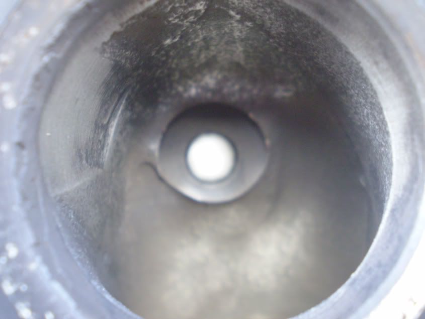
Now let’s take a look at this bowl, and see what can be improved:
As always, remove any porous casting marks and carbon completely from the entire bowl/port as you please. The exhaust shouldn’t be as bad as the intake was. Are you still doing all these one item at a time in all six ports before moving on? Good, don’t want to get ahead of yourself.
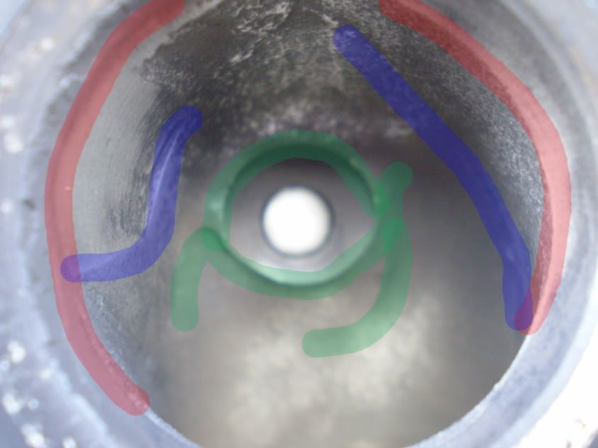
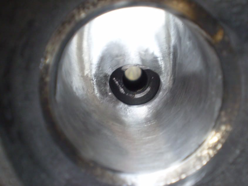
The green in here represents the valve guide. As in the last one, remove the ridges around it completely. If you decide to do the portion nearest the port as well, be sure not to take too much material off or to damage the inside of the valve guide.
The blue represents hard casting lines that are separate from the bowl area and the actual runner itself. Take these out and remove the humps that they surround in the bowl area similar to that of the intake bowl.
The red is a very sharp casting that completely surrounds the valve seat. Since this is the exhaust port, we need not to worry about hindering flow by removing this on either the bowl or short side radius. The short side radius side is especially bad in this case, and is probably reason for a lot of the restriction in the exhaust as a whole. Be careful once again with the valve seat.
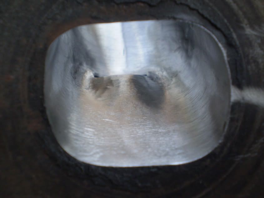
Now, let’s take a look at the exhaust port. I should note that the D shape of the port is very important to the scavenging effect of the motor. The bottom of the port that isn’t rounded and seems like a restriction is what is called the “reversion dam”. It prevents back pulses of exhaust gas from going back into the cylinder. Leave this alone. Once again I’m not making the port any bigger, so this won’t be a concern here.
The exhaust port shouldn’t take much time all. As always, remove all porous casting marks.
The green represents the valve guide. There is a large hump here that can be removed for the most part. As I’ve said before, avoid damaging the valve guide. The humps wing off toward the valve a bit too, don’t miss it.
The blue are harsh casting lines inside the valve that go down into the bowl area (remember those?). Remove them, blend them, and avoid the valve seat at all costs.
The red is another view of the ridge around the valve seat that I mentioned earlier; here you can see just how sharp it is. Blend it in well.
Results:
What everybody wants, results. And I have some tested and tested again. I’d like to add in here that this is not the first set of heads I’ve done, and these are by far from complete. This is about the most basic port/polish job that a person could tackle. Your results may vary, but from the different sets I’ve don’t and tested, they are pretty on par. You could spend much more time on your own set than I cared to do and they would look much nicer. My exact cfm numbers may be off, but since the experiment was constant the percentile gain should be on par.
Intake: Here the results seemed pretty average. Not much was improved, but a gain is a gain. An average of 1.5% or so on low lifts, and a little more on high lifts.
Lift Cfm (stock) Cfm (polished) Gain
.0 2 2 0
.1 53 55 2.8
.2 112 113 .06
.3 147 150 2.0
.4 171 172 .05
.5 180 183 1.6
.6 180 185 3.2
Exhaust: Now this is where things become interesting. I was so impressed the first time that I flow benched a 3800 head that I literally tested the port with a stock port a dozen times. I also had other people bench them and benched additional ports on other heads for comparison. Incredible 15% gains without even considering making the port any larger or gasket matching!
Lift Cfm(stock) Cfm(polished) Gain
.0 2 2 0
.1 47 47 0
.2 96 103 7.2
.3 116 133 15.1
.4 130 151 15.9
.5 136 157 15.1
.6 137 157 13.8
Conclusion:
I hope this guide helps those of you who like to save a little money but want performance. A basic port and polish job is a quick an easy way to get some extra oomph out of your 3800. These heads will not do as well as a vendor port job, but with extra time and effort you could probably make a set that are comparable. As you can see, even small changed can give large gains.
Let the flaming commence. For the record, the port job i did on the ports i took pictures of was less than an hour job."
Hope some people find this as useful as I did! Chris


