OK folks, since I botched the rebuild of my 4T65E I decided to do what I should have done to begin with. I found a GM manual that explains exactly how this thing works, including hydraulic schematics. Since I work with electronics by trade, I am more comfortable reading these. In an attempt to figure out what went wrong with my rebuild, I am studying everything I can about this transmission. I will not be an expert by any stretch of the imagination, but at least I will be a well-informed idiot.
One thing I have learned so far is that due to the unbelievable complexity of this system, it is virtually impossible to troubleshoot/diagnose anything more than the basic problems that these transmissions are known for (i.e., bang shifting, sudden loss of 4th, etc, etc…) over the Internet. I applaud those brave souls who try to help those like me as much as they can. Guys like Dave (Trannyman) at TEP and Billboost must pull their hair out at times. They have my utmost respect and admiration for what they try to do.
So, in my endeavor to understand how transmissions (well, the 4T65E anyway) work, I am going to pass on what my perceptions are as I understand it better. I find that I learn better if I write things down. Since I’m writing it all down, I thought I would share what I learn along the way.
IMPORTANT NOTE: I am NOT a transmission expert! I never will be. DO NOT take what is written here as transmission gospel.
Another IMPORTANT NOTE: If you decide to tear into your transmission based on what you read or saw in another thread or on a different forum, I caution you now…learn how the dang thing works before you even drop the pan. Just because someone else managed to pull it off without a hitch doesn’t mean your tranny rebuild will be as straight-forward. There are many tiny things that can be wrong. So, learn how it works, and learn what to look for as best as you can.
OK enough lecturing…just the dad in me coming out. Without further ado (did I really just say that???) Here is first gear from a hydraulic standpoint. I’ll do a mechanical standpoint (how the hard parts work) later…because I don’t know yet.
Buckle your seatbelt…here we go…
When the car is placed into drive, the manual valve routes line fluid into the D4 fluid circuit. If I understand the hydraulic schematics and operation correctly, D4 fluid is just a fancy name for the fluid circuit used to operate each individual gear set. In other words, D4 is line fluid after it passes through the manual valve.
The manual valve also stops PRN (Park, Reverse, Neutral) fluid and allows it to exhaust. Since PRN is holding the #3 check-ball open, this exhaust action allows input (1st gear) clutch fluid to seat the #3 check-ball. Well, it has to do other things first, but I’ll get to that later.
Now, when Line fluid exits the manual valve as D4, it does a couple of things. For one, it goes to the TFP switch and activates D4. It also travels to the 2-3 shift valve and passes through the 2-3 valve as auxiliary input clutch apply fluid. This happens because the 2-3 shift valve is being held in the downshifted position by 2-3 signal fluid via the energized 2-3 shift solenoid.
At the same time, D4 fluid also seats the #6 check-ball and travels to the FWD band servo, applying the FWD band. If you are romping the gas when shifting to D, fluid is also routed to the FWD boost valve to help fill the FWD servo faster.
At this point, since the 1-2 shift solenoid is energized, it blocks 1-2, 3-4 signal fluid from exhausting, which forces the 1-2 shift valve against the spring and into the downshifted position.
Fluid now passes through the 1-2 shift valve where it now becomes LO/1st/Input (whatever you want to call it) fluid. This input fluid then unseats the #10 check-ball, and passes through the 2-3 shift valve (which is still being held in the downshifted position), then through the 3-4 shift valve (also being held in the downshifted position by 2-3 signal fluid).
Now, finally, Input fluid unseats the #3 check-ball, travels through the CP to the driven sprocket support, through the support and into the input clutch hub (between two of those bastige Teflon seals) and into the input clutch housing where it forces the input clutch piston against the clutches.
Let me go through this one thing at time to make sure I understand what could go wrong here.
Starting with the Manual valve: If the Manual valve were leaking bad enough, Line fluid would exhaust along with PRN fluid (or leak into other channels, resulting in the same thing, a drop in D4 pressure). This would cause slipping of 1st gear at the very least and no apply of 1st at all in a worst case.
TFP: If the switch were bad, I would suspect the PCM would recognize a problem and set a code, although I cannot confirm that.
The #6 check-ball: If this check-ball is leaking there would be reduced or even no flow to the FWD servo. In other words, the FWD band would not apply and even though the input clutch is applied, you won’t go anywhere.
1-2 shift solenoid: Since this solenoid should be energized, and therefore closed, 1-2 3-4 signal fluid pressure should increase holding the 1-2 and 3-4 shift valves in the downshifted position. If this solenoid is de-energized (due to an electrical malfunction, etc) or is leaking, 1-2 3-4 signal fluid could exhaust allowing the 1-2 and 3-4 shift valves to move against spring pressure. If this happens, there would be no fluid pressure to the input clutch, hence, no first gear.
#10 check-ball: If this check-ball is stuck closed, again, no fluid to the input clutch and no 1st gear.
2-3 shift valve: If this valve is leaking, I suspect there could be a problem (fluid could be allowed to exhaust). Since the valve opening is much larger than the leak could be, I wouldn’t expect to see a complete loss of 1st gear though (there may be considerable slipping though). However, I’m no expert so don’t take my word for it. In any event, this would be the last place I would look for a problem with 1st gear. On the other hand, if this valve is stuck in the up-shifted position, no fluid could get to the input clutches. If this were to happen, there would be more problems than just no first gear.
3-4 shift valve: See 2-3 shift valve above, basically the same scenario.
#3 check-ball: This check-ball could be a real problem if it’s leaking or stuck open. That would cause Input fluid to exhaust along with PRN fluid. I suspect this would cause a serious drop in line fluid and a badly slipping or no 1st apply.
Driven sprocket support: Unless it’s badly worn, or the apply port is plugged up, I don’t see it being a real problem. Anything is possible though.
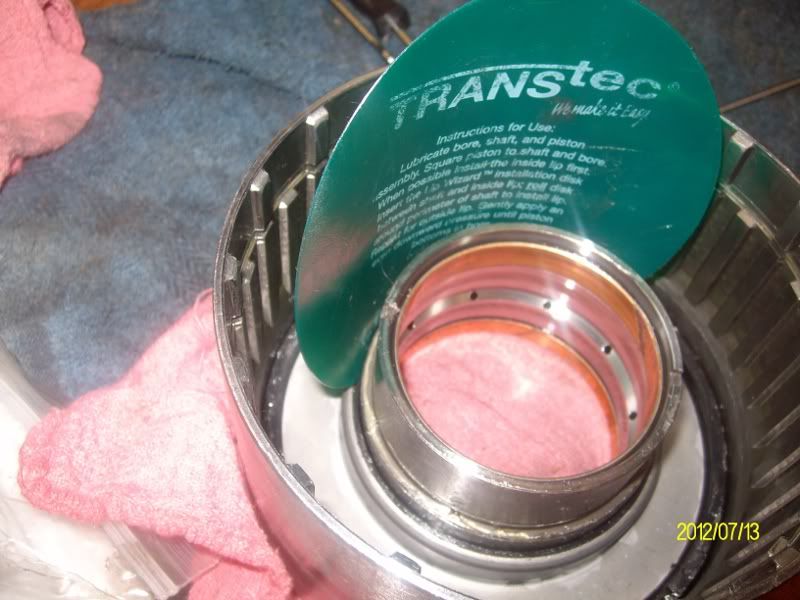
Input clutch hub: The potential for a problem is there. This hub/shaft uses Teflon seals to direct apply fluid to the input and 3rd clutches. Leaking seals could easily cause slipping or no apply of 1st gear.
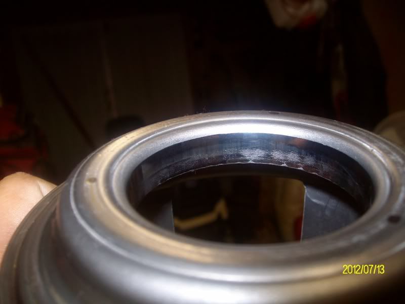
Input clutch piston: This piston is famous for wearing out. Once this thing wears out enough, no 1st gear, or at least bad slipping.
Here is my old one:
OK, that’s my understanding of how 1st gear operates, from a hydraulic standpoint. If any part of this is not correct, please let me know so I can correct it.
EDIT: It occurred to me that there is no accumulator for 1st gear. My assumption is that the FWD servo sort of acts like an accumulator, if you think about it. As input fluid is being applied to the clutch housing, it is also going to the servo to apply the FWD band. I suppose if the servo piston became stuck, the input clutches would probably bang together. Of course, if the piston was stuck, you probably wouldn't feel the bang because the FWD band isn't applied (because the piston is stuck). Just my curious ramblings here...